Scrambler82
Old Bastard !

Joined: Fri Dec 22nd, 2017
Posts: 2108
Name: Grev B ... Occupation: Quality Assurance Engineer ... Interests: Rangers, Photography, Metal Bending ...
Reputation Points: 2108

|
12o Wrote: "Our best advice would be to pick another circuit.. and maybe find a second opinion for Ranger resources. Just kidding, maybe your partner there misunderstood your intentions for an ignition based circuit (?)..
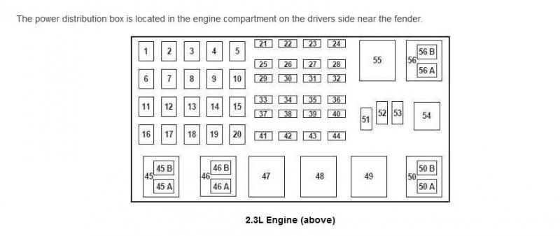
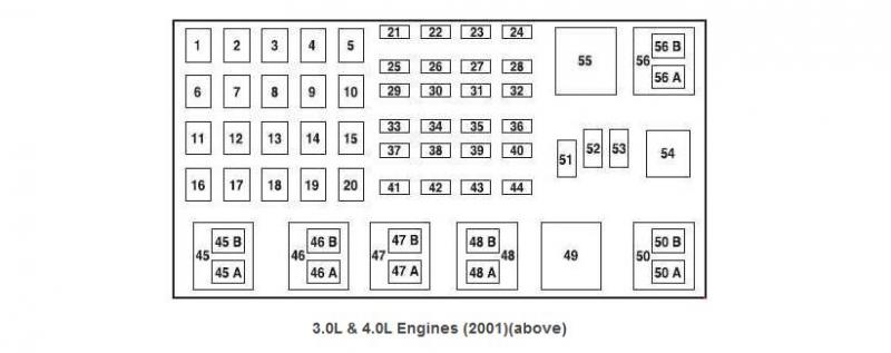
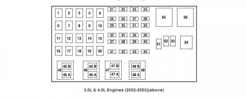
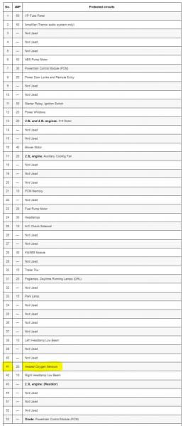
You would want to use Circuit [31] 20A fog lamps, Daytime Running Lamps (DRL)
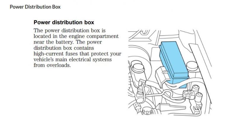
Assuming you're wanting to keep this wiring underneath the hood, I would take the time to pull the OE Power Distribution Box itself. It has 2-3 clips that hold it into place, a gentle prying motion in the right direction will release the panel and a slight tug x2 should give you enough room to rotate the panel to view the underside.
But before you do that, I would ask that you take a really good picture of your opened Power distribution box so we can see whats what in it."
Me:
I took out the Engine Bay Fuse/Relay Box; two screws and a slide in mount for the Bracket... PITA to get the six clips out to remove the bottom cover.
I found Fuse #F1-31 but it has Power to it all the time, it isn't what I wanted/need.
I looked up fuse #F1-31 DRL Circuit, 20 amp, and found that it feeds #F2-2, located inside of the truck and it is a 10 amps; it states Hot on Run... that would work but I need to check out the actual wire... a Black w/Light Green.
I now need to ring out the wires, with and without power on, to see where it goes and if the wire loses power without the key on.
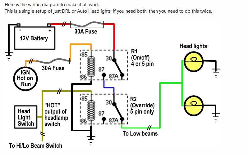
If ANYONE thinks this is the wrong approach or there is a different route to achieve a "Hot on Run" Circuit feel free to post.
Thanks to 12o for the assist.Last edited on Sun Sep 26th, 2021 09:39 am by Scrambler82
____________________
Ltr,
2003 EDGE, Std Cab, Steppie, E4 Red, 5sp, 4x
5" SuperLift, 33" x 12.50 x 15"
Hurst Shifter
Mod'd Backrack to fit Steppie
Front and Rear Bumpers by Custom 4x4 Fabrication, OK; now Mike's Welding and Fabrication.
Working on more Mods, just need more time, longer days would work !
|