Ford-Rangers.com Ranger Forum HomeFord-Rangers.com Ranger Forum Home
Home Recent Topics New posts Search search Menu menu Not logged in - Login | Register
Ford-Rangers.com Ranger Forum > Tech Section > Member's Projects Showcase > 410Custom's builds a 2007 Ranger V8 - cu

Ford-rangers.com is a discussion forum, a Ranger forum for people who have questions about fixing or modifying
their Ford Rangers or people who just admire their Ranger. Please join and enjoy sharing experiences!

410Custom's builds a 2007 Ranger V8 - cu       #: 1712
 Moderated by: NoPower, Mike69, MaDMaXX, Page:  First Page Previous Page  ...  5  6  7  8  9  10  11  12  13  14  15  Next Page Last Page  
New Topic Reply
 Rating:  Rating
 Posted: Mon Sep 26th, 2022 03:17 pm
PM Quote Reply
226th Post
Eddie Money
Member


Joined: Mon Nov 13th, 2017
Posts: 1587
Name: 
Occupation: 
Interests: Burt gummer life ...
Status: 
Offline
Reputation: 
Reputation Points: 1587
"Added by eddie, posted by 410custom"


new fuse added


Leads to be used later hanging off the back
Sjb good to go


Alternator wiring wrapped
moving on


____________________


I know my crazy! Do you?
2007 Sport 4door 4x4 4.0L SOHC V6 Ranger
Back To Top PM Quote Reply

 Posted: Mon Sep 26th, 2022 03:30 pm
PM Quote Reply
227th Post
Eddie Money
Member


Joined: Mon Nov 13th, 2017
Posts: 1587
Name: 
Occupation: 
Interests: Burt gummer life ...
Status: 
Offline
Reputation: 
Reputation Points: 1587
"Added by eddie, posted by 410custom"

shes going to need a steering column

The 07 column needs some mods, column pulled from storage, cleaned and dusted


First up we will be console/floor shift!!!!!!!!!
So the whole column shifter OD button and park interlock go bye bye


going to need to source a non column shift shroud, or mount something cool here later?


As discussed before PATS not needed


halo/wiring removed from column

Truck is prepared the holley PCM battery harness was run through the firewall and into engine bay then the steering went into the dash


Holley wires going through factory wiring grommet


routed, PCM has power

Floor wiring: seats, t case/bed wiring in place


Look ma clean floors

Floor laid back down
Steering in........ first look at the Holley PCM completely connected (one red wire to ignition switch, that's next)
There is talk of using a different steering wheel or re wrapping this one.... after truck is running/driving


[url=https://www.explorerforum.com/forums/threads/410customs-builds-a-2007-ranger-v8-custom-truck-build-project-ranger-premier.481492/reply?quote=3963933][/url]

it is loose, not mounted, I have not chosen the final location yet... the new console is quite roomy underneath
However the shifter will take up a bunch of space. I would like to make the led's visible, we shall see

This is how I splice into the run/start power feed at the ignition switch


and the holley PCM wiring at the battery


You bend the little tabs back and the terminal tighten bolts will come out, then I clean between the clamp with emery board and install the new ring terminal


Ignition wires installed


I am using these Motorcraft wires until the Taylor wires I ordered for this truck get here (backorder till October!)
These wires are leftover from another project


intake started

Last edited on Mon Sep 26th, 2022 03:45 pm by Eddie Money


____________________


I know my crazy! Do you?
2007 Sport 4door 4x4 4.0L SOHC V6 Ranger
Back To Top PM Quote Reply

 Posted: Mon Sep 26th, 2022 03:46 pm
PM Quote Reply
228th Post
Eddie Money
Member


Joined: Mon Nov 13th, 2017
Posts: 1587
Name: 
Occupation: 
Interests: Burt gummer life ...
Status: 
Offline
Reputation: 
Reputation Points: 1587
"Added by eddie, posted by 410custom"

With every truck build there is a final junk yard trip I usually have a 5 speed ranger around I can snag that cowl from, otherwise I can find in the yard or on eBay! Thanks for helping!! I'm making a checklist of the final final stuff before I turn the key and aetup the Holley hopefully later today! I have fitted oil filter and 5 quarts of Mobil one is in the engine
Trans fluid, t case, coolant and then let's see how this goes


____________________


I know my crazy! Do you?
2007 Sport 4door 4x4 4.0L SOHC V6 Ranger
Back To Top PM Quote Reply

 Posted: Mon Sep 26th, 2022 03:47 pm
PM Quote Reply
229th Post
Eddie Money
Member


Joined: Mon Nov 13th, 2017
Posts: 1587
Name: 
Occupation: 
Interests: Burt gummer life ...
Status: 
Offline
Reputation: 
Reputation Points: 1587
"Added by eddie, posted by 410custom"

okay added fluids, put in battery, turned the key to on
The Holley lights up like Christmas
I went through the setup wizards, then setup the tps, then monitored all sensors.
I have read the Holley setup guide about 1000 times, this time I went through it very carefully followed step by step instructions.......

The Holley is happy, all green lights. However no starter and no fuel pump!!!!

I have some wiring to sort out........ likely due to changes between the 05 and 07 harness, and possibly still due to the 07 instrument cluster not liking me for removing pats

Good thing I know a wiring guy! Up early, been bugging me all night. I will sort this out today!
I have a complete 05 dash and wiring if needed (I doubt it)

GOOD NEWS, Holley PCM appears to be happy and working just fine............. this is progress!!


____________________


I know my crazy! Do you?
2007 Sport 4door 4x4 4.0L SOHC V6 Ranger
Back To Top PM Quote Reply

 Posted: Sun Oct 9th, 2022 01:52 pm
PM Quote Reply
230th Post
Eddie Money
Member


Joined: Mon Nov 13th, 2017
Posts: 1587
Name: 
Occupation: 
Interests: Burt gummer life ...
Status: 
Offline
Reputation: 
Reputation Points: 1587
"Added by eddie, posted by 410custom"

the holley pcm has one wire to control the fuel pump

I have it triggering the stock relay similar to factory, however the Holley PCM sends a 12V+ signal, the factory PCM sent a ground. So for this truck I grounded out the fuel pump relay and sent the 12V+ fuel pump control to the VPRM feed on the fuel pump relay, so the Holley triggers the + feed of the relay.
. Fuel pump power from fuse, through stock relay, triggered by pcm, power through inertia switch to pump. My problem is in the wiring I used, I am using a 07 dash with a 05 under hood harness, there are some slight changes I need to overcome. I found the fuel pump wires from the 05 harness right now they are not going to the fuel pump!! I will use a test light and confirm the signal is present.
This is OKAY I expected this............ I can wire up a starter and fuel pump in my sleep. Just needed to know what hoops to jump through next. The 07is a little bit different then all the trucks I have done before......
That has never stopped me

Last edited on Sun Oct 9th, 2022 01:54 pm by Eddie Money


____________________


I know my crazy! Do you?
2007 Sport 4door 4x4 4.0L SOHC V6 Ranger
Back To Top PM Quote Reply

 Posted: Sun Oct 9th, 2022 01:55 pm
PM Quote Reply
231st Post
Eddie Money
Member


Joined: Mon Nov 13th, 2017
Posts: 1587
Name: 
Occupation: 
Interests: Burt gummer life ...
Status: 
Offline
Reputation: 
Reputation Points: 1587
"Added by eddie, posted by 410custom"

Well I hit the books yesterday, spent a few hours with my 2005 ranger and 2007 ranger wiring books, identified 36 of the 49 wires at the C144 plug

enough to know that the 2005 and 07 dash harness is way out from each other
I have learned ALOT about the differences between the old style OBD PCM and the newer can bus systems.......


So I will be re wiring this dash backwards to a 05........... this is why I kept a complete 05 interior. wiring, etc I knew this was a possibility
So today I will be swapping out the dash wiring, fixing one plug that feeds the fuel tank and tail lights........ THEN try again! Hang tight!!


____________________


I know my crazy! Do you?
2007 Sport 4door 4x4 4.0L SOHC V6 Ranger
Back To Top PM Quote Reply

 Posted: Sun Oct 9th, 2022 02:00 pm
PM Quote Reply
232nd Post
Eddie Money
Member


Joined: Mon Nov 13th, 2017
Posts: 1587
Name: 
Occupation: 
Interests: Burt gummer life ...
Status: 
Offline
Reputation: 
Reputation Points: 1587
"Added by eddie, posted by 410custom"

I have the wiring solved, I THINK LOL

After comparing three dash boards with their prospective wiring, I decided the easiest path forward was to remove the 05 engine bay harness and install the original 097 engine bay harness, as long as I could identify the 18 wires I need to interface with the truck.

So I did just that. After many more hours with the 07 ranger wiring book and the actual 05 and 07 wiring on the shop floor I was able to locate all the wires I need. So then I unbolted everything that was in the way from the ABS pump to the Radiator and AC condenser all the way around to the cruise control controller......and just like that the 05 wiring is out.
Then I prepared the 07 wiring
And now it is about to go back in.
Once this is complete I expect to have all of this sorted out! and be able to start the truck
There is only ONE wire that does not have a home in the 07
The Overdrive off indicator light from the Holley PCM to the instrument cluster....the 07 instrument cluster does not have separate wires for each light anymore instead the cluster and the PCM just talk over the can bus system. So I will need to be clever and add a OD off light .... I did however notice that the ABS controller has the ability to turn on a "tow mode" light bulb in the cluster so I may be able to use that.

Next up we shall see how happy the 07 is with my decisions  Hopefully the next post or two will be with a running truck

2007 dash next to a 2005 dash, there are quite a few differences as far as wiring goes! However this 07 dash (left) and the 07 dash in the truck appear to be identical, so I'm guessing all 07-11 trucks will be the same.
Also the 05 dash appears to be just like the 01-04 sports and sport tracks I am used to dealing with.


2007 harness being customized getting ready to go back into the truck it originally came from

WHAT A RIDE!!!!!!


____________________


I know my crazy! Do you?
2007 Sport 4door 4x4 4.0L SOHC V6 Ranger
Back To Top PM Quote Reply

 Posted: Sun Oct 9th, 2022 02:01 pm
PM Quote Reply
233rd Post
Eddie Money
Member


Joined: Mon Nov 13th, 2017
Posts: 1587
Name: 
Occupation: 
Interests: Burt gummer life ...
Status: 
Offline
Reputation: 
Reputation Points: 1587
"Added by eddie, posted by 410custom"

I bet we find similar across the board for Other fords too

Its a really neat system, there is WAY LESS wiring
it does make it more difficult to do this

The C110 (c112, C115) 42 pin square plug went away at the same time they switched so it would be easy to tell
ALL of our RBV had the 42 pin plug from 95-2005
I am not sure if the 06+ explorer, sport trac and others made the switch too, but I am guessing they did

At the end of the day I am met with two challenges SO FAR, there maybe more coming.
The instrument cluster, usually I can hack into them and move wires around, add signals, etc
Not anymore............
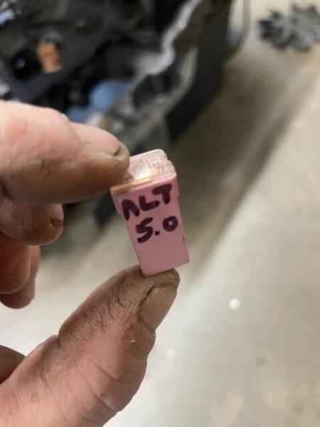
For a 5.0 swap I have no way to hookup the OD cancel light and the coolant temp sensor!!!!!!!!!!!!!! These signals now come from the pcm via can bus to the cluster.........well the pcm went bye bye. So a custom cluster of sorts will have to be created, I do not want to leave a non working coolant gauge in the dash, also the theft light will always flash with no PCM....

I could have easily just ripped all the 07 out and replaced with a say 96 style dash, use a 05 cluster so it looks just like an 07 but where is the fun in that? the 05+ trucks have the fuse panel in the passenger kick panel, everything is completely different, I wanted to keep as much 07 as possible (retain the ABS computer, Restraints computer, speed control computer, 4x4 control module), etc etc.........and here we are


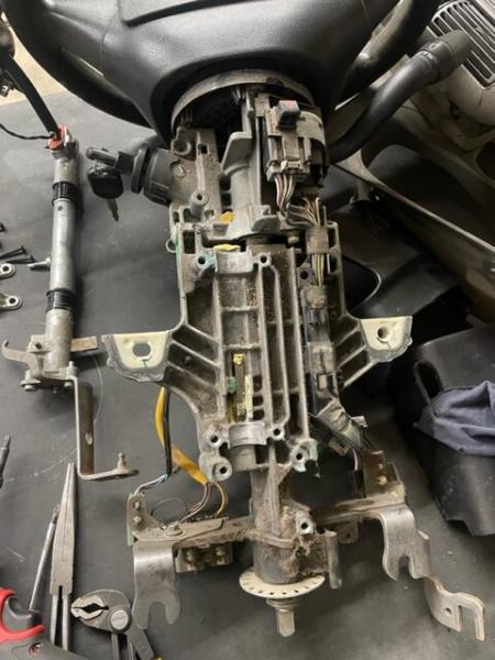
Last night I finished preparing the 07 wiring, identified the 11 wires I need to hookup the holley, and now I am adding the C110 plug to the 07 harness and then finally it can go back in, plug and play!
I still expect some issues, a custom instrument cluster and subsequent wiring is in my future
My goal is starter and fuel pump, with those two things she will run
Then I can worry about wiring up a custom cluster to look legit.


____________________


I know my crazy! Do you?
2007 Sport 4door 4x4 4.0L SOHC V6 Ranger
Back To Top PM Quote Reply

 Posted: Sun Oct 9th, 2022 02:03 pm
PM Quote Reply
234th Post
Eddie Money
Member


Joined: Mon Nov 13th, 2017
Posts: 1587
Name: 
Occupation: 
Interests: Burt gummer life ...
Status: 
Offline
Reputation: 
Reputation Points: 1587
"Added by eddie, posted by 410custom"

 I am in Holley setup land, been reading for two days about setting up the PCM

I have fuel pump, I have 65 psi and it holds 55 psi for like 12 hours after shut down!
I have starter......at first we had no spark.

then I went to school, online Holley setup school. Talking to Brett asked a few quick questions and got some answers.
I learned that first I needed to update the firmware in my Holley, our kit is from 2019 there have been about 20 updates to the operating system since then. Easy enough, I brought the SD card inside, loaded up the latest firmware from Holley website and tried setup again
BLAMO! Now we are talking, so many more choices for setup!!
Now I have spark, but its not right, backfire through the intake
So back to school I went.........now looking at Mustang and Early Bronco dudes and how they setup the stock cam and crank sensors.......
I am now waiting on a $62 Holley cable that will allow me to tune the Holley software with tablet/laptop/pc

I am EXTREMELY happy with the progress, all systems on the truck side of things appear to work thus far.
Details to come and HOPEFULLY a video if her running.
While I wait for the cable to come in the mail and learn more about the base tune we need for this setup I am working on other things like airbox and muffler install, shifter and shift cable, etc........

Hang in there (especially you Tim I will be more help to you after I learn all this stuff I am sure you have already schooled yourself on) and yes I may need to put the cam sensor 185 degrees out for the Holley........ we shall see!!


____________________


I know my crazy! Do you?
2007 Sport 4door 4x4 4.0L SOHC V6 Ranger
Back To Top PM Quote Reply

 Posted: Sun Oct 9th, 2022 02:04 pm
PM Quote Reply
235th Post
Eddie Money
Member


Joined: Mon Nov 13th, 2017
Posts: 1587
Name: 
Occupation: 
Interests: Burt gummer life ...
Status: 
Offline
Reputation: 
Reputation Points: 1587
"Added by eddie, posted by 410custom"

the camshaft rotates 1 times vs the crank rotates 2 times.

the piston will reach TRD twice, both times the crank mark is at the pointer
once on compression stroke and the second is on the exhaust stroke = 180 degrees out.

This means that the crank mark for 0 DTC will be at the pointer both times
even with the camshaft 180 degrees out
The crankshaft damper uses the same mark for tdc compression and tdc exhaust
The stock damper also has marks for 10 degrees ATDC all the way to 10 degrees BTDC


____________________


I know my crazy! Do you?
2007 Sport 4door 4x4 4.0L SOHC V6 Ranger
Back To Top PM Quote Reply

 Posted: Sun Oct 9th, 2022 02:06 pm
PM Quote Reply
236th Post
Eddie Money
Member


Joined: Mon Nov 13th, 2017
Posts: 1587
Name: 
Occupation: 
Interests: Burt gummer life ...
Status: 
Offline
Reputation: 
Reputation Points: 1587
"Added by eddie, posted by 410custom"

Okay, in order to set the camshaft sensor 180 (or 185-190) "out"
it really means we are going to set the cam sensor with cylinder one at TDC on EXHAUST stroke
The 0 mark on your balancer is used, not a mark on the opposite side
so the wheel you printed would not work!


I drew a simple diagram to help us visualize. (Please ignore the spelling errors LOL It was at 5 am this morning and at that hour I am a little bit dyslexic, O TDC!!)

Basically right now the cam synchro is set on the cam tooth based on the crank being at TDC compression
I need to reset the cam sensor to be on the cam tooth when the crank is at TDC exhaust stroke. The synchronizer will be pulled off the cam tooth and reset in the o DTC exhaust position.
This is 180 degrees of rotation on the cam tooth

For me to set the cam synchro at 185 degrees I can simply go to TDC (0) and then move it ATDC to the 5 degree mark, now drop the synchronizer in.
I really hope this helps!!

I will be lowering the truck this morning and resetting my cam sycnhro to 185 degrees out
I installed the two spin tech mufflers and exhaust to them
I fully expect the truck to run today
Fingers crossed


____________________


I know my crazy! Do you?
2007 Sport 4door 4x4 4.0L SOHC V6 Ranger
Back To Top PM Quote Reply

 Posted: Sun Oct 9th, 2022 02:08 pm
PM Quote Reply
237th Post
Eddie Money
Member


Joined: Mon Nov 13th, 2017
Posts: 1587
Name: 
Occupation: 
Interests: Burt gummer life ...
Status: 
Offline
Reputation: 
Reputation Points: 1587
"Added by eddie, posted by 410custom"

Not running yet, but I think we have it sorted out as to why
Hang in there...... I've barely slept (obsessed OCD)
I am now fluent in Holley terminator software, handheld, global files and Explorer 302 terminator setup using stock explorer electrics, coil packs and stock cam crank sensors.....
We have some new information and I need to move a couple of wires around
truck is cranking and trying to fire, we tried many many things yesterday (testing and tuning) and now I think we know what the issue is......


____________________


I know my crazy! Do you?
2007 Sport 4door 4x4 4.0L SOHC V6 Ranger
Back To Top PM Quote Reply

 Posted: Sun Oct 9th, 2022 02:09 pm
PM Quote Reply
238th Post
Eddie Money
Member


Joined: Mon Nov 13th, 2017
Posts: 1587
Name: 
Occupation: 
Interests: Burt gummer life ...
Status: 
Offline
Reputation: 
Reputation Points: 1587
"Added by eddie, posted by 410custom"

New information coming in about how to properly time the cam synchronizer for the terminator X


Moving the wire I was speaking of yesterday was simply re routing the power for the cam synchronizer to pin B20 on the Holley. They want the power for the cam and crank hall effect sensors to come from this pin on the PCM, this is considered "clean power"
So I took the power feed away from the PJB and gave it directly to this pin
No change

So far we have tried:
putting cam synch 185 out
moving dedicated power wire for cam/crank
checked air/fuel spark
checked my power feeds
Checked for power at iac, injectors, etc power dist from holley
Checked PCM pinout to sensors making sure all is correct and connected
about 10 different setups on the software side, most of this is just me learning the proper setup for this engine/ignition/sensors with the holley

BUT GOOD NEWS!

It looks like I stabbed it at 10 degrees after top dead center on the exhaust stroke and that maybe too far
it should be closer to 10 degrees BTDC on exhaust

going to try again today

Holley is very specific about when the cam sensor must occur

Right now everything is green, crank the engine over, it attempts to fire but does not. The cam and crank sensor lights go blue green blue green just like they are supposed to, except the crank sensor led goes red after a few rotations. This is telling us there is an issue with the crank sensor.
The stock crank sensor is a VR magnetic type which as everyone knows requires shielding. These two wire sensors can be "noisy" and difficult to setup (software) with the Holley, so a "hall effect" type sensor is preferred (3 wire)
I have ordered one from Lowdollar motorsports for $79
This will help the Holley run our SBF smoothly and consistantly

However with the new info/ help I am getting on the classicbroncos forum I think we have found the issue, cam synchro is still out!!

So new hope...... It can be like going to war, each day you have a new plan and then somewtimes no gains......rollercoaster.
But this is what drives us!! This is the CHALLENGE!! So far all of my conversions are still on the road, I fully expect this sucker to work

This is my first Holley but I doubt it will be the last.


Here is the thread on the early bronco forum, while researching our setup I found some dudes who already have these running around AND posting their info and findings........

Windsor 5.0 Explorer Motor Wiring with Waste-Spark Coils
I started with a mustang 5.0 config then changed the ignition settings to custom with attached settings. At that point I believe if fired up and I noticed the sensor (oil, water temp & fuel pressure ) didn't seem accurate, don't overheat your engine! I spent copious time with multimeters and...
classicbroncos.com


I love going to school and learning each day, as we get older we need less and less sleep anyways!!

Last edited on Sun Oct 9th, 2022 11:01 pm by Eddie Money


____________________


I know my crazy! Do you?
2007 Sport 4door 4x4 4.0L SOHC V6 Ranger
Back To Top PM Quote Reply

 Posted: Sun Oct 9th, 2022 02:12 pm
PM Quote Reply
239th Post
Eddie Money
Member


Joined: Mon Nov 13th, 2017
Posts: 1587
Name: 
Occupation: 
Interests: Burt gummer life ...
Status: 
Offline
Reputation: 
Reputation Points: 1587
"Added by eddie, posted by 410custom"

making sure exhaust stays away from future driveshaft!!


Here's the deal
setting the cam sensor 185 degrees before tdc cyl 1 on compression stroke is NOT SIMILAR to having your distributor (or cam sensor) 180 degrees out of time!!!
That is where I got confused

when setting up Holley terminator X for a Ford with cam and crank sensors information on the web says to "set your cam sensor 185 out"
To me that is setting the dist on tdc exhaust stroke as we discussed, and 5 degrees away from that.
The actual instructions from Holley are to Set the cam sensor 185 degrees before top dead center

LIKE THE PICTURE, with the crank rotated 185 degrees before TDC occurs...........
Two totally different things!!!
Now I have clear direction and will report back


____________________


I know my crazy! Do you?
2007 Sport 4door 4x4 4.0L SOHC V6 Ranger
Back To Top PM Quote Reply

 Posted: Sun Oct 9th, 2022 02:14 pm
PM Quote Reply
240th Post
Eddie Money
Member


Joined: Mon Nov 13th, 2017
Posts: 1587
Name: 
Occupation: 
Interests: Burt gummer life ...
Status: 
Offline
Reputation: 
Reputation Points: 1587
"Added by eddie, posted by 410custom"

WE HAVE A RUNNING TRUCK!!!!!!!!!!!!!!!!!!!!!


THANKS TO BRETT and my new buddies on the Classic bronco forum
We found all issues, solved them and now she fires right up!!


Video coming


what a rollercoaster!!!!!!
https://classicbroncos.com/forums/conversations/cam-sync.1006389/#convMessage-1016025


____________________


I know my crazy! Do you?
2007 Sport 4door 4x4 4.0L SOHC V6 Ranger
Back To Top PM Quote Reply

 Posted: Sun Oct 9th, 2022 02:27 pm
PM Quote Reply
241st Post
Eddie Money
Member


Joined: Mon Nov 13th, 2017
Posts: 1587
Name: 
Occupation: 
Interests: Burt gummer life ...
Status: 
Offline
Reputation: 
Reputation Points: 1587
"Added by eddie, posted by 410custom"

yes for the holley it is required

Well actually it is required to be a min of 100 degrees btdc, but it is good practice to set it at 185 BTDC because Holley actually provided the formula to calculate this location back in like 2012
I will explain later in the thread, first lets get to what fixed it
We need to get Tims truck running!!! With these two things we are hopeful his sport will finally fire
He has similar coil wiring to me, as he followed my diagram!

Let me show you how WE fixed the truck. I say we even though I am the only one working on the truck. A whole slew of people came together to help me through this.
Brett was the one to show me the final "trick" to get her to fire, on a "hunch" (from experience!)
To be fair, the same idea was pitched on the classic bronco forum at around the same time, but I was still confused thinking they were talking cam sensor not crank

First off the crank balancer
"Lucky for us the stock balancer has a carved groove at 180 making this spot/tooth easy to identify
Now turn the engine clockwise (15/16 socket on crank) until your 185 mark is on the engine crank pointer

Now turn the balancer around one more time
The second time the 185 mark comes around to the pointer is the correct location


Now install cam synchronizer alignment tool
Stab 3 wire synchronizer into block, install hold down and hold down bolt
Install cam sensor
DONE


Here is the CORRECT diagram to show how we get to 185 


I have a spare crank balancer


Here is the CORRECT diagram to show how we get to 185 degrees BTDC


Factory balancer is 36-1, so each tooth = 10 degrees of rotation
With the timing pointer set to the 0 mark the crank sensor actually sits two teeth back from the 0 mark
the missing tooth that the crank sensor detects, (1 pulse per rotation) is three teeth forward of the 0 mark
So the timing offset on the stock balancer is - 5 teeth (this is important for holley software setup)


HERE IS 185 degrees BTDC on stock 5.0 balancer

Same mark CAREFULLY made on truck AND in position at timing pointer


Time to use the alignment tool and stab our synchronizer


This is the proper flag location


Notice with the alignment tool removed the flag is leaving the window as it passes by the cam sensor
This is DIGITAL FALLING which is preferred for tuning with the Holley, this is important for software setup

Cam synchro done!!


here is important info from Holley about setting up the PCM to run with cam and crank sensors


Magnetic & Hall-Effect Crank/Cam Sensor Setup - Holley Performance Products Forums
* There's an updated version of "Crank & Cam Sensor Setup" in the Holley EFI software. On the top Toolbar, click "Help" & "Contents". It's listed in the Help topics. * Originally Posted by Danny Cabral If your crank or cam sync unit isn't transmitting a signal, troubleshoot
forums.holley.com


what we are doing:


"Cam sync location (degrees BTDC #1) = "Ignition Reference Angle" + “A” + (“A” / 2)

“Ignition Reference Angle” = Taken from Crank Sensor Setup in software
“A” = Angle Between Crank Pulses (crank degrees between triggers on the crank sensor)

“A” for a 8 cylinder = 90°
“A” for a 6 cylinder = 120°
“A” for a 4 cylinder = 180°
Using the formula above, plug in the “Ignition Reference Angle” you are using and the proper “A” value depending on the number of engine cylinders.
The location calculated is the “ideal” location and can vary +/- 30° or possibly more.
If you are out of this range contact Holley Tech Service for options.

Click to expand...


Yakleys69 notes from Classicbroncos forum:

these are my notes: probably from multiple sources that I extrapolated what was relevant and likely wrote it in a way that I understood.
Cam Sync setup
Purpose is to identify when cylinder #1 is coming up.
Cam makes 1 rotation for every 2 rotation of the crank. Every other TDC cylinder #1 fires.

The cam sync signal trigger MUST occur:
* BEFORE cylinder #1 is at TDC on the COMPRESSION STROKE
* It also must occur at least 50 degrees BEFORE the “missing tooth” read by the crank position sensor.

“Ignition Reference Angle” = Taken from Crank Sensor Setup in software
“A” = Angle Between Crank Pulses (crank degrees between triggers on the crank sensor)

  • “A” for a 8 cylinder = 90°
"Ignition Reference Angle" + “A” + (“A” / 2) = Cam sync location (degrees BTDC #1)
50 + 90 + 45 = 185

Click to expand...


The rest of my notes on this. no need to print out degree wheel each tooth is 10 degrees. Put on TDC mark teeth as needed. 36-1 trigger has 35 teeth missing one so 36 x 10 = 360

Crank Sensor ( 50° BTDC = Ignition Reference Angle )
Missing tooth is used to identify the Crank Position,
Other teeth are used for RPM and timing

Put Engine at TDC (engines rotates clockwise)
* This will be compression stroke of cylinder 1
* Can tell by placing finger over plug hole
* Also it will be after the intake valve opens, if you can see it

Crank Trigger is 36-1 tooth
* Every tooth is 10 degrees
* With engine at TDC , The crank sensor is on the 5th tooth
* So the ignition offset is 50 degrees

Note: the Ignition Reference Angle set in the software is is typically set to a value that is 10° more than the highest timing you will run. Do NOT set it higher than 75°.

Click to expand...


Next My wiring diagram for the coil drivers
I found a couple of mistakes on my coil driver wiring map from earlier in this thread

Last edited on Sun Oct 9th, 2022 11:03 pm by Eddie Money


____________________


I know my crazy! Do you?
2007 Sport 4door 4x4 4.0L SOHC V6 Ranger
Back To Top PM Quote Reply

 Posted: Sun Oct 9th, 2022 02:36 pm
PM Quote Reply
242nd Post
Eddie Money
Member


Joined: Mon Nov 13th, 2017
Posts: 1587
Name: 
Occupation: 
Interests: Burt gummer life ...
Status: 
Offline
Reputation: 
Reputation Points: 1587
"Added by eddie, posted by 410custom"

Wiring MISTAKES!!
I must eat crow for two things

First I was wrong earlier!

Tim's degree wheel DOES WORK!!!
Second, I had two pins backwards on my chart AND I reversed 4 wires after a coil driver

this caused me to be combining 4 cylinders incorrectly at the coil packs!!
truck was misfire and backfire during cranking!! Not good

It is fixed now
Let me show you how


I had typed 8, 7, 6, 5 instead of 5 6 7 8 and that caused a snowball effect

The file has now been corrected, as has the wiring at the truck

Basically I had to remove the coil pack and coil drivers
I labeled all 8 cylinder signal wires with their number (flags on tape)
Then I could see where I was way off! Basically combining the wrong cylinders for the waste fire coils


The purple ink shows how things were wired incorrectly. The correct wire combinations shown in graphite direct from ford wiring schematics for our coil packs


With all 8 wires labeled for their cylinders based on the pin locations from Holley it was clear to be way off. This caused misfires and backfires

Easy enough to fix on the bench

I compared holleynwiring information to my chart and found some mistakes
Then I went and confirmed the truck is wired from pcm all the way to the coil drivers 100% correct (phew)
The only changes needed were after the odd side Coil driver
Everything else was correct

Tims truck used the same wiring diagram and is having similar misfires and backfires during cranking
We are
Hoping with this information about the cam synchro and the coil wiring his truck will also decide to run!!


Attachments


Last edited on Sun Oct 9th, 2022 03:01 pm by Eddie Money


____________________


I know my crazy! Do you?
2007 Sport 4door 4x4 4.0L SOHC V6 Ranger
Back To Top PM Quote Reply

 Posted: Sun Oct 9th, 2022 02:39 pm
PM Quote Reply
243rd Post
Eddie Money
Member


Joined: Mon Nov 13th, 2017
Posts: 1587
Name: 
Occupation: 
Interests: Burt gummer life ...
Status: 
Offline
Reputation: 
Reputation Points: 1587
"Added by eddie, posted by 410custom"

This is what we do!!!

Thank the guys at the classicbronco Forum Yakelys69 is the one who posted up the info on how he got his explorer running. The rest of the internet is just bits and pieces of info scattered all over, no real good thread for setting up the explorer 5.0 with the Holley Terminator X!
Truck is running, but it still needs tuned
I just wanted to hear it fire so I can move forward with the rest of the build!!


____________________


I know my crazy! Do you?
2007 Sport 4door 4x4 4.0L SOHC V6 Ranger
Back To Top PM Quote Reply

 Posted: Sun Oct 9th, 2022 02:47 pm
PM Quote Reply
244th Post
Eddie Money
Member


Joined: Mon Nov 13th, 2017
Posts: 1587
Name: 
Occupation: 
Interests: Burt gummer life ...
Status: 
Offline
Reputation: 
Reputation Points: 1587
"Added by eddie, posted by 410custom"

Speaking of moving forward with the build

decided to use a stock airbox, slightly modified, for this truck. We did not want to run an open element under the hood, there are no good aftermarket airboxes made for the ranger, and the ones that are out there for Jeeps and such are $$$$

So lets modify some stock parts
I need a good way to connect the intake tube to the airbox
This is the job of the factory MAS


So I gutted one, we do not need the sensor and we want more airflow so


housing was filed smooth inside. I left some "meat" at the top to enable me to plug the hole


hole was drilled and tapped to accept threaded plug


set flush inside


cleaned and JB welded so no air leaks


housing cleaned and painted


____________________


I know my crazy! Do you?
2007 Sport 4door 4x4 4.0L SOHC V6 Ranger
Back To Top PM Quote Reply

 Posted: Sun Oct 9th, 2022 02:51 pm
PM Quote Reply
245th Post
Eddie Money
Member


Joined: Mon Nov 13th, 2017
Posts: 1587
Name: 
Occupation: 
Interests: Burt gummer life ...
Status: 
Offline
Reputation: 
Reputation Points: 1587
"Added by eddie, posted by 410custom"


airbox mods
The stock v8 airbox allows a little more air in then the v6 box
Still not enough for my liking so


I added a second intake “horn” and shaved them both down a bit, this should allow more cool air in from behind the headlight


Both glued in place


Completed v8 airbox


Now the v8 box mounts slightly further away from fender then the stock ranger box so


Difference is 1” out
Drill new holes, paint bare metal, re install bracket


Fits like stock!!


Everything buttoned back up and we have a running truck


Last edited on Sun Oct 9th, 2022 02:53 pm by Eddie Money


____________________


I know my crazy! Do you?
2007 Sport 4door 4x4 4.0L SOHC V6 Ranger
Back To Top PM Quote Reply

 Posted: Sun Oct 9th, 2022 02:56 pm
PM Quote Reply
246th Post
Eddie Money
Member


Joined: Mon Nov 13th, 2017
Posts: 1587
Name: 
Occupation: 
Interests: Burt gummer life ...
Status: 
Offline
Reputation: 
Reputation Points: 1587
"Added by eddie, posted by 410custom"

Okay here it is! Video from the first start

It is not very good video as I fully did not expect it to start. I had been trying different things for 3 days before this and each time it would just crank and crank, sometimes with misfires and backfires. So when it actually started it really caught me off guard!! I scrambled to get my phone and shoot a short clip, then thought "I better shut it down and check things out"
Soon after I tried to start her again.
Now she comes to life with the bump of the key

The FINAL fix to get it running was to SWAP the CRANK sensor wires side to side
Right now I am using a stock magnetic VR type crank sensor. The holley was not happy with our crank signal, resulted in a red light after cranking (6th diagnostics led is for crank sensor)
Brett said I should try swapping the sensor wires side to side on a "hunch" he had seen this before.
Access to the crank sensor on the 5.0 SUCKS
But I realized I could simply swap the PCM signal wire and the ground feed at the ignition adapter, took 1 minute.
There was a dude on the classic bronco forum who suggested I do this also, however I was confused thinking we were still discussing cam sensors. So thanks to @Brett and @EPB72 for the suggesting. Reversing the crank sensor PCM ground and signal wires worked! It reverses the wave form or field coil or something like this, it made the Holley happy


So I did, then tried to crank the truck
IT FIRED!!!!!
I was so taken back it actually scared me......... it coughed, backfired one time (likely left over fuel) and then started running and smoothed out!!

That is when this video was taken


13 seconds of pure relief and awesome!
It was like 3:30 in the afternoon and I was still on my slippers, basically get out of bed start troubleshooting truck hahahaha

I will still be installing a hall effect type crank sensor when it arrives, it is a better setup for tuning and reliability


____________________


I know my crazy! Do you?
2007 Sport 4door 4x4 4.0L SOHC V6 Ranger
Back To Top PM Quote Reply

 Posted: Sun Oct 9th, 2022 10:21 pm
PM Quote Reply
247th Post
Scrambler82
Old Bastard !


Joined: Fri Dec 22nd, 2017
Location: California USA
Posts: 2108
Name: Grev B ...
Occupation: Quality Assurance Engineer ...
Interests: Rangers, Photography, Metal Bending ...
Status: 
Offline
Reputation: 
Reputation Points: 2108
Wow, what a project.
I didn't think it would take this long, right now I'm glad I didn't try to do it myself.

Looks good.


____________________
Ltr,
2003 EDGE, Std Cab, Steppie, E4 Red, 5sp, 4x
5" SuperLift, 33" x 12.50 x 15"
Hurst Shifter
Mod'd Backrack to fit Steppie
Front and Rear Bumpers by Custom 4x4 Fabrication, OK; now Mike's Welding and Fabrication.
Working on more Mods, just need more time, longer days would work !
Back To Top PM Quote Reply

 Posted: Mon Oct 10th, 2022 07:26 am
PM Quote Reply
248th Post
JAMMAN

Owns A Torsen


Joined: Mon Sep 18th, 2017
Location: Grove City, Ohio USA
Posts: 6429
Name: Jim ...
Occupation: 5 axis cnc programmer ...
Interests: RBV's ...
Status: 
Offline
Reputation: 
Reputation Points: 6429
I actually read that whole thing! The vid was awesome, you would expect jumping around and "WOOHOO! It's been 2 years listen to this!" then running out the truck to the front to show rotation "Wow the pulleys are spinning no backfires! This is the greatest day in human history!"

All completely contained by a true professional and packaged as... "Guess what? It's running."

Not all hall effect switches are created equal. What frequency is the top for that one... I have had ones on machines cack out if there were too many triggers per rev. Worked great at low RPM's then the minute it reaches a decent RPM a line forms across the screen where the numbers used to be. Looks like the cam synch is handling the incremental pulses the crank PROBABLY just needs one?

Thanks Eddie for mirroring the article, it certainly is a premium build thread!


____________________
00 XLT 4WD RCSB 3.GO! Jalapeño
01 XLT 2WD RC Steppie 3.0 auto Silver
The future belongs to those who show up.
Back To Top PM Quote Reply

 Posted: Wed Oct 12th, 2022 05:23 pm
PM Quote Reply
249th Post
410customs

Idahome


Joined: Wed May 2nd, 2018
Location: Panhandle, Idaho USA
Posts: 2165
Name: Jamie ...
Occupation: Elevator Design Worlds Tallest Buildings ...
Interests: Ranger Based Vehicles and OFFROAD ...
Status: 
Offline
Reputation: 
Reputation Points: 2165
I fully did not expect it to start, had been like 12 previous attempts
All I did before this start that was different was reverse polarity at crank sensor
Now I have installed a hall effect style sensor and wiring to it, also fixed cam synchro timing again (I was still 180 out LOL)
There is more coming to this thread........ I am still putting seats in her, but also multitasking
More big updates coming soon
It has been a slow build, many changes in my life over last 2 plus years, but the end goal remains the same, build Eddie a Ranger the way I would do it and treat it as if it was my own
Making a BIG PUSH NOW to get truck DONE!
IT RUNS!!!!!!!!!!!!!!!!!!!!!!!!!!!!!!!!!!!!!!!!!!!!!!!!!! Trust me I almost cried tears of joy that night, weeks of fillding went into getting it sorted and running on all 8, she sounds sooooo good


____________________
I build custom RBV, specializing in drivetrain conversions, wiring, suspension and complete custom trucks
Back To Top PM Quote Reply

 Posted: Mon Nov 21st, 2022 04:17 pm
PM Quote Reply
250th Post
Eddie Money
Member


Joined: Mon Nov 13th, 2017
Posts: 1587
Name: 
Occupation: 
Interests: Burt gummer life ...
Status: 
Offline
Reputation: 
Reputation Points: 1587
"Added by eddie, posted by 410custom"

the 07 CANBUS cluster will need to be hacked

Tach and coolant, od off light, not going to work there is no way for me to input to them
Plus the theft light is just flashing away non stop
The cluster is just resting in there for testing

I have two other similar clusters (05 and 06 ranger) as well as many gen II clusters I can use for parts
That is one of the next challenges

I may have to bust a 05 ranger cluster apart so I can get to the meat and potatoes, then using parts from a gen II cluster make it function...and if that will work I will have to add just about every cluster wire a Gen II needs. Right up my alley!
I do NOT want to have to use a Holley digital dash, we like stock looking and that is more $$$$$$$$$$

Worst case scenario we will use all aftermarket gauges and make some LED indicator lights.....??? We shall see


Right now I am making a "to do" list
there is lots to do to get Eddie his truck back, but at least its getting short enough to fit into a LIST!
I have slight exhaust leak at drivers header, did not look too much into it yesterday, could be at collector, could be at gasket? will see

The trans only has 5 quarts of fluid in it right now
This was INITIAL startup just to PROVE the wiring and plumbing to the drivetrain are SORTED!!!!!!!!!!!
WOOOHOOOOOOOOO

lots of cleanup/fab/install still to do

Seat install is another biggie, the center console and shifter, need to install ARB air line, compressor and a mountain of electrics


____________________


I know my crazy! Do you?
2007 Sport 4door 4x4 4.0L SOHC V6 Ranger
Back To Top PM Quote Reply

Current time is 03:56 am Top Page:  First Page Previous Page  ...  5  6  7  8  9  10  11  12  13  14  15  Next Page Last Page    

Ford-Rangers.com Ranger Forum > Tech Section > Member's Projects Showcase > 410Custom's builds a 2007 Ranger V8 - cu

Users viewing this topic


PHP Version: 8.2.28
Server version: 10.6.21-MariaDB
UltraBB 2.01.01 Copyright © 2008-2025 Jim & Chris
Page processed in 0.1120 seconds (42% database + 58% PHP). 107 queries executed.