mhoward
Hey look ~ they ~ bounce!

Joined: Sun Oct 22nd, 2017
Posts: 2751
Name: Michael ... Occupation: Technology Manager ... Interests: Trucks / Guitars & Music / Things that go BANG ...
Reputation Points: 2751

|
 How to Install a Factory Parking Aid (Reverse Sensing) System How to Install a Factory Parking Aid (Reverse Sensing) System
There are several names for this feature
Parking Aid System
Parking Assist System
Reverse Sensing System
Reverse Warning System
Regardless of the name you choose to call it, for simplicity, this article will use the term Parking Aid.
######################################
# Why Retrofit an OEM Parking Aid System?
######################################
There are several aftermarket parking aid systems on the market. These are mostly Chinese systems and can be purchased on eBay or Amazon for nearly nothing I bought one on eBay for $15.99. Before it even arrived, I developed buyer's remorse because in order to install them, I have to drill holes in my chrome bumper (my PERFECT, hard-to-find, chrome FLARESIDE bumper). Now, drilling the holes isn't what worried me. What *DID* worry me was after installation, if a component of this system failed, I most likely couldn't get replacement parts for it and then I would be stuck with a holey bumper. By retrofitting an OEM system, parts are plentiful and will be available for YEARS to come, thereby ensuring my installation will be easily repaired if need be. An added benefit of going OEM is that it is more robust than the lightweight Chinese knockoff parts that looked and felt like a toy.
######################################
# Obtain Salvage Parts from a Donor Vehicle
######################################
For this mod, I chose a 2000 Lincoln Navigator as the donor vehicle. At the time, it appeared to be the only vehicle in the Pull-A-Part yard that had the system intact. This vehicle had been on fire (dashboard wiring) so it was a mess. After pulling all the parts, I later found a 2000 Eddie Bauer Explorer in really decent shape that didn't have weeds growing up around and under it. That was the vehicle I salvaged the sensor bezels from; as they are angled correctly to fit the Ranger rear bumper (the Navigator bezels were not). ALL of the parts could have been salvaged from this vehicle, but I chose to stick with what I had already pulled. I highly recommend using the Explorer parts if you can find one. An added benefit is that the gauge cluster trim panel is where the disable switch is located. You can salvage this piece along with the rest and you won't have to fabricate the switch mounting (provided the color is right). Please note that the disable switch from the Navigator is completely different from the Explorer, in both shape and placement. So, here is what you will need to get from your donor vehicle:
Consists of:
4) Rear bumper sensors (it would be advisable to get a couple of spares from other similar vehicles)
4) Locking sensor bezels (from Explorer, Expedition or F150)
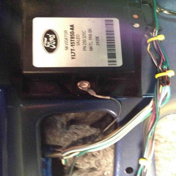
1) PAM (parking aid module) includes the warning speaker
1) Parking aid switch (disables the feature)
1) Gauge cluster trim panel (optional if you are using an Explorer as the donor vehicle)
######################################
# Component Photographs
######################################

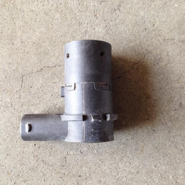


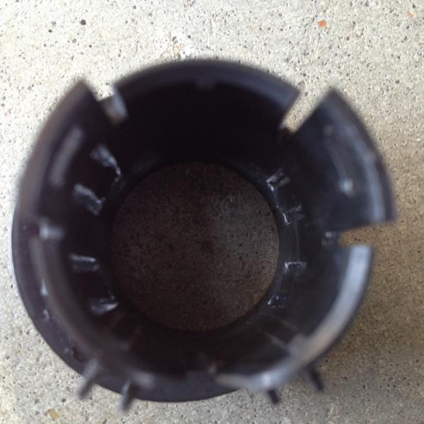


Once you have everything, take a little time to clean it all up. The sensors reside in the bumper, which catches a lot of dirt, sand and the like. Clean parts are easier to work with and will perform better. Don't forget to clean all connector contacts with some good quality contact cleaner!
######################################
# Wire Colors / Wire Function
######################################
Sensor wire colors:
WH/LG Left / Outside
DG/WH Left / Inside
BN/PK (4 - common to all sensors)
DG/YE (4 - common to all sensors)
WH/LB Right / Inside
DB/YE Right / Outside
Speaker wire colors:
BK/PK Signal
DG Ground
Parking Aid Module wire colors:
GY/YE Hot in run
BK/PK Reversing Lamps (+12V)
DG/VT Parking Aid disable switch
VT/OG Parking Aid disable switch
LB/WH Data Link Connector (DLC)
BK/LB Ground
WH/LG Left Outside sensor
DG/WH Left Inside sensor
BN/PK Common to all sensors
DG/YE Common to all sensors
WH/LB Right Inside sensor
DB/YE Right Outside sensor
Parking Aid Disable Switch wire colors:
DG/VT Parking Aid Module
VT/OG Parking Aid Module
BK/LB Ground
LB/RD Instrument Illumination (illuminated switch)
######################################
# Bench Testing the Parking Aid System
######################################
Bench testing the system is quite simple. Just connect the wires together matching color codes. Follow the wire codes above to supply the power and ground from a power source (a good 9V battery will work just fine for testing). You can ignore the LB/WH (DLC) wire for this test. Ensure the sensors are all facing away from the module and switch and aren't pointing toward each other or anything. Supply power to the system and note if it beeps. If it does not, press the disable switch once to enable the system (although it should default to on when power is applied). If you are standing in front of the sensors, the system should make an audible beep sound. Moving away from the sensors should stop the beep. You can check that the sensors are all working by listening to each one individually while the system is activated. You will hear a faint clicking / ticking sound (a stethoscope is quite helpful for this). If you don't hear this sound, the sensor needs to be replaced. In the photo below, I have it temporarily wired for bench testing. Note that the disable switch is different from the components photos above. I chose to use the switch from the Explorer as the one from the Lincoln looked pretty rough from the heat of the fire, although it *DID* function correctly.

######################################
# Parking Aid System Installation
######################################
 NOTE: I strongly encourage you to use solder and shrink sleeve when performing the installation. The extra time and effort spent will ensure you have a reliable, long lasting and trouble-free system. NOTE: I strongly encourage you to use solder and shrink sleeve when performing the installation. The extra time and effort spent will ensure you have a reliable, long lasting and trouble-free system.
Remove the radio and bezel. Using solder and shrink sleeve:
Connect switch to truck harness inside dash (2 wires)
BK/LB Ground
LB/RD Instrument Illumination (illuminated switch)
Drill radio bezel and mount Parking Aid Switch (unless using the Explorer trim panel and switch)
Make a thin cardboard template that fits the switch snugly. Transfer this shape to the proper location on the radio bezel (or an alternate location of your choice). Drill a 3/4†hole and carefully shape it with a round file or Dremel tool to the template you made until it snugly fits the Parking Aid disable switch
Snap the switch into place and plug it in

For the next two steps, I used a length of CAT5e cable:
Extend wiring from switch to control module (2 wires)
DG/VT Parking Aid Module
VT/OG Parking Aid Module
Extend wiring from control module to inside dash (3 wires)
GY/YE Hot in run
BK/PK Reversing Lamps (+12V)
LB/WH Data Link Connector (DLC)
Punch a hole in the oval floor grommet directly under the jack pocket & feed the sensor cable through


Extend wiring from control module to rear bumper harness (6 wires)
WH/LG Left Outside sensor
DG/WH Left Inside sensor
BN/PK Common to all sensors
DG/YE Common to all sensors
WH/LB Right Inside sensor
DB/YE Right Outside sensor
NOTE: I used a length of CAT6 data cable for this, which has 4 pairs of wires and a tough sheathing
Route and secure the wiring along a safe path from the controller location to the rear bumper
Mount the controller to the cab to the left of the right rear speaker using self-tapping sheet metal screws

Seal hole in the grommet with RTV once the cable has been connected to the module and zip-tied into place
Connect control module to chassis (1 wire)
BK/LB Ground
Solder a ring terminal to this wire and place it under the lower module mount screw (as shown)
Plug sensors into bumper harness and tape them to the face of the bumper
CAREFULLY determine position (Left ~ Right), height (20" to 27") and spacing of the sensors (14†apart Max)
Tape the sensors to these positions and TEST

If system functions correctly:
Replace any trim panels that were removed to facilitate mounting of components or routing of wires
Cover bumper with heavy duct tape
Layout sensor placement on bumper (check BEHIND bumper for obstructions)
Center punch, drill pilot hole, then drill out to 1-1/8th diameter using a step bit
File edges of holes to remove any burrs
Trim the keyways off the bezels with a sharp razor knife
Test fit sensor bezels
Paint holes with Rust-oleum to prevent rusting (let dry 24 hours)
Snap bezels into holes and use a small amount of epoxy or JB Weld to prevent them from rotating (if needed)
Once the epoxy / JB Weld has cured, insert sensors and lock into place (my installation didn't need this)
Plug the harness into the sensors, ensuring the connectors lock and zip-tie it up out of the way
Test system functionality one more time, then run these system checks:
######################################
# Azimuth System Check
######################################

######################################
# Elevation System Check
######################################

######################################
# Finished Product!!!
######################################


Last edited on Mon Nov 13th, 2017 08:38 am by mhoward
____________________
-- Michael
2003 Ranger Edge / Extended Cab / Flareside / 3.0L FLEX / 5r44e Auto / 2WD / 8.8 LS 4:10 / Sonic Blue Pearl
So many mods... so little time...
|