Eddie Money
Member

Joined: Mon Nov 13th, 2017
Posts: 1587
Name: Occupation: Interests: Burt gummer life ...
Reputation Points: 1587

|
"Added by eddie, posted by 410custom"
here we can see the holley wiring has made its way into the cab! (Cab floor needs a cleaning Yes I see that too!)

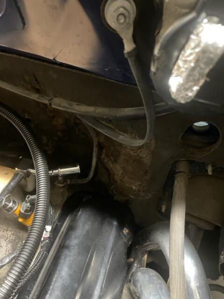
now to sort out some of the hurdles. I had to figure out a fuel line and power steering high pressure hose solution. The 07 Ranger is different from the earlier trucks, the stock fuel line runs up the spine of the v6 transmission. The high pressure PS hose also mounts to the track differently.
I found a 02-05 4.0 power steering line is able to be made to work.


PS line will need some bending to be perfect, but it works


has a funky bend in it, could have a custom line made if needed by modding this one, but lets see if we can make this one work even with its funky routing. I have a large line bender that really helped to shape it


PS line sorted!!
The fuel line I snagged from a 02 sport trac, plugs into the 5.0 and plugs into the 07 style fuel filter.
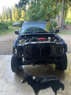
Time for some routing and under hood mods, lets get this 5.0 put together!

the stock 5.0 starter/ ground/charging harness has this metal bracket that ties into the explorer frame. It keeps the wire loom away from the oil filter and fan, so we will re use it. To make it fit the ranger frame better I cut it up a little bit, drilled a pilot hole and mounted it with a self tapping screw. here you can see I am using a C clamp so I can bend the tangs and free its grip from the wire loom
Install the top "tab" the ranger frame has a spot for it, then mark the hole on the bottom where to drill (oval mark)


arm cut off, hole drilled
While we have the grinder out might as well take care of two more brackets

When running a 1" intake spacer the coil tower and throttle cable holder need some mods. Basically cut off some bits

parts removed, let the mods begin!

All parts sent off to the parts washing department (me)
Wiring bracket final install


Everything is cleaned and prepped before install, need to find a home for the coil drivers


Meanwhile, remember this little gem? I dug the cv axle out so I can ship it to RCV for repair...... fingers crossed 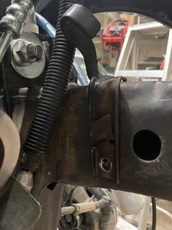


Next items to be wired to the Holley harness, IAC, TPS, CTS, and coil packs. Factory 5.0 pigtails soldered to Holley wires, wires cut to fit my under hood routing.

Holley oil pressure sender installed to the 5.0, just then I realized I will need two oil pressure sensors, one for the stock dash also. So I ordered a dual mount for a 302 from Ebay, $30

Once it arrives I can install both sensors

Messing around with fuel lines, somehow I ended up with two 06-11 Ranger lines? I also tried a 05 ranger line, it would have needed an adapter, then finally I found the 02 sport trac line will be plug and play. Had to swap the heat shield also on the ranger frame...they are different in 06+ more on that later

factory heater hose manifold cleaned and painted, ready for install. Also can see the 02-05 style fuel line heat shield
final routing for the crank and cam sensor wires

behind the heater hoses lol

heater manifold installed to engine

liking this location for the Holley 4 channel coil drivers, make it so

You can see the Holley coil pack (ignition) wiring has been routed down the drivers valve cover, wrapped and loomed.
Heater manifold and hoses installed. The fuel injector harness was final wrapped and installed. Cam and crank sensor wires routed...this engine bay is ready to go together!!
test fitting the upper plenum, getting some measurements for possible COP/ LS coil install

2.5" clear under plenum on drivers side, this is with the 1" intake spacer

tons of space on the passenger side

3.5" vertical clear at top of valve cover
5.5" at the bottom

Now I need a EGR block off plate for the back of the intake plenum/elbow. Time to fabricate!

Gasket is traced onto 1/4" plate


band saw and grinder, then a hand file and BLAMO
EGR block off, oh yeah I cut a new gasket too


Speaking of plugging up the EGR
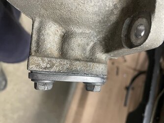
the new Drain plug / TMH EGR bung plug arrived today
stainless 22mm 1.25 pitch drain plug with gasket
Will get some anti seize and final install. I ordered two, I am sure I will need another one of these!


Before the intake goes on the engine ground strap is added

Now soldered

Built a simple mount for the two 4 channel coil drivers, really happy with how this turned out


test fit / perfect!!


Alternator wiring, AC line routing being sorted, most things are just like a factory 5.0
Our owner really likes a stock ish under hood engine bay
This one is clean and well sorted
I have plans for the upper intake paint job Shhhhhhh

Each coil driver needs a ground directly to the corresponding head.
These coil tower, lower intake bolts go directly into each head.
Perfect

final paint


I changed up the vacuum line a little bit for the back of the intake. Now it has two feeds, one for the fuel rail damper and the second will be for the Holley PCM built in MAP
sensor
well, since the Ford ignition is waste spark and only uses 4 coils....... I am wondering if I can combine cylinders BEFORE the coil driver and then just use ONE 4 channel coil driver instead of two.....
This is how we learn! By doing.
coil drivers ARE needed for CNP or COP ignition, I confirmed w Brett
more on wiring the waste spark ignition and mounting of the coil drivers. I am very happy with how this turned out!

bracket back from final paint shop (me), here you can see how the holley ignition harness is routed along drivers side injectors and to the back of the coil tower

the TMH, EGR block off plug is installed fully, anti seize on the threads. This is a 22mm 1.5 pitch drain plug (not 1.25 like I said earlier)
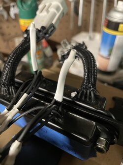
Now before I cut the Holley plugs off the coil drivers on the coil pack side of things I needed to carefully mark the wires with their corresponding pin letters, as you can see all of the wires are black, so this is very important to get it right. I triple checked before I cut a wire. The connectors are labeled very faintly with letters. I used a black marker and wiped it off on the white plugs, so I could see the letters clearly. On the black plugs I could not do so, so I used tape

On the output side of things (coil pack side) wires A-D are the coil driver wires (signal) and wires E-H are the red power to coil wires, all 4 wires E-H are the same, basically switched power to coil. I only need one red wire on each coil pack, for good measure I used two and capped the other two off


Coil drivers marked, one feeds cyl 1-4 and the other 5-8< DO NOT MIX THEM UP!!!!! Very important that cyl #1 wire leaves PCM, goes through coil driver, and ends up at Cyl 1 coil..... same is true for cyl 2-7. This wiring was done very carefully, checked several times along the way before final wrap!!

At the end of the day (or ignition coil harness) we only have 6 wires
Why? Because the Ford waste spark only uses 4 coils.
The chart I made earlier shows this very clearly, ALSO the PDF file WILL BE updated, earlier I had the wires labeled wrong!!
I am working on updating it today (06/20)

here you can see two coil signal wires come together to feed a single coil.
Wiring is done per the PDF chart I posted earlier, MUST BE DONE PERFECTLY!!!!!! or you can destroy your engine (not likely) but Holley makes it very clear you must have a professional (like me) install this system. A full understanding of why this is wired the way it is is needed, do not just copycat something you see on the net, you need to know the ifs, whys and buts of this wiring. Your harness may use different pin locations or wire colors! Mine is a Holley kit made for the Ford 302 and 4r70w, the injector harness and main harness match up. Then I custom wired the GM coil on plug ignition harness to be a Ford waste spark ignition. CAREFUL folks.Last edited on Tue Jul 26th, 2022 01:33 pm by Eddie Money
____________________
I know my crazy! Do you?
2007 Sport 4door 4x4 4.0L SOHC V6 Ranger
|