mhoward
Hey look ~ they ~ bounce!

Joined: Sun Oct 22nd, 2017
Posts: 2751
Name: Michael ... Occupation: Technology Manager ... Interests: Trucks / Guitars & Music / Things that go BANG ...
Reputation Points: 2751

|
 How To: Power To Accessory Circuit After Key Off How To: Power To Accessory Circuit After Key Off
All credit for this mod goes to Bob Wenzing (rwenzing). Many thanks to Bob for his creativity, expertise and willingness to share his knowledge to help others mod their vehicles!
I found this information in an old thread and noticed that the diagram Bob referred to was missing. I contacted him and he graciously emailed the missing diagram to me 12 years after his original posting! Bob, you are awesome!
######################################
# Original Post
######################################
Note: This is an unauthorized mod that I did to my 2003 Ranger for my own reasons. I present it here for informational purposes only. If you choose to do something similar, you do so at your own risk.
This is a simple mod that will provide power to the accessory circuit (including radio, power windows & wipers / washers) after the ignition switch has been turned off. The accessory circuit will remain powered until the driver's door is opened. As pictured below, it should work on 2001~2003 Rangers and possibly earlier years as well. The 2004+ Ranger is a different beast electrically and this will not work as written for 2004-on.
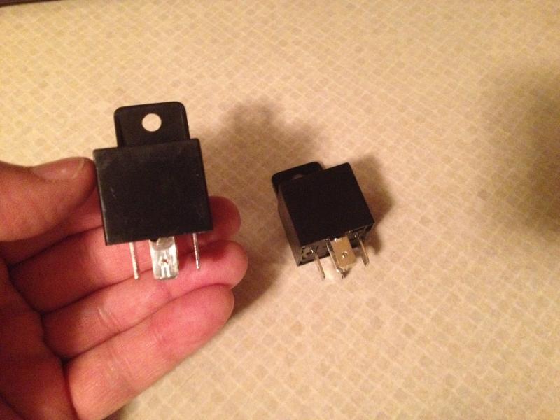
It requires 2 standard Bosch pattern SPDT relays which are available at the Ford dealer for about $7 each - a good one to use is a replacement for a Ranger's heater blower motor relay. It is easy to connect wires to the relay pins using quality 1/4" insulated spade terminals or special relay sockets.
All wires are readily accessible in the radio cavity with the radio removed. It may make things easier if the radio bezel is also removed.
NOTES:
***There are two yellow/black's in the drawing: one to the GEM and one to the HU. They have different functions and must not be interchanged nor connected together.
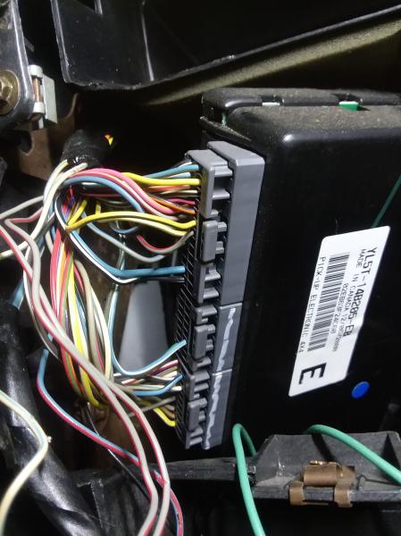
***The GEM module has two connectors. The yellow/black (yellow wire with a black stripe) to be tapped for the door open signal is in the connector closest to the front of the truck. CAUTION: There is also a black/yellow (black wire with a yellow stripe) in the same connector - be careful not to mix them up.
***I used 16 gauge wire throughout to match the truck wiring. The spade connectors and wire taps used should also match the 16 gauge wire.
***Pin 30 of the relay on the right side of the diagram should be tapped to the Black/Light Green wire of the dash harness going to the head unit. There are two of these Black/Light Green wires and the larger one should be used.

######################################
# My Version
######################################
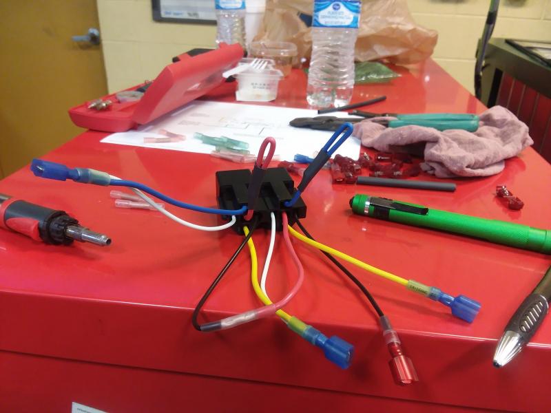
Here is how I did mine, using a pre-made dual relay connector and relays from Parts Express (http://www.parts-express.com)
Parts needed:
1) 330-078 12 VDC Bosch Type Dual Relay Socket for Door Lock/Unlock Circuits
2) 330-073 12 VDC Automotive 5-Pin Relay SPDT 30/40A Bosch Type
4) ------------ wire taps
These relays have a mounting tab molded onto the housing, making it an easy mount. I used the same relays and connector on my autolamps mod and they have performed flawlessly for over two years as of this writing (11/2017).


I then labeled the relays A and B and created the following chart for reference.
Relay A Wire Destination of Wire
Pin Color
30 Blue To Relay B Pin 86 AND GN/PU on audio head unit
85 White To Relay B Pin 87A
86 Black To YW/BK on audio head unit
87 Yellow To YW/BK on audio head unit
87A Red Not Used
------------------------------------------------------------------------------------------------------------------
Relay B Wire Destination of Wire
Pin Color
30 Blue To LARGE BK/LG on audio head unit
85 White To YW/BK on GEM
86 Black To Relay A Pin 30 AND GN/PU on audio head unit
87 Yellow Not Used
87A Red To Relay A Pin 85

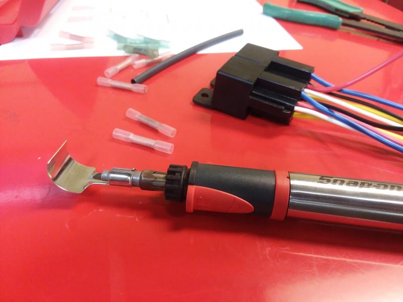
I then followed the diagram and tapped the appropriate wires together, soldering and shrink tubing the connections. On the wires for the unused poles, I simply cut the wires off short, bent them over and shrink tubed them.

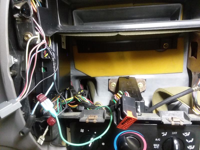
Into the dashboard we go! I removed the radio and bezel, then made the appropriate connections, again per the diagram using wire taps as it is pretty tight in there for soldering. Although I am not fond of wire taps, sometimes it is necessary due to working space constraints. I then mounted the relay assembly to the screw holding the bottom of the upper duct. A 7mm socket will do the trick. I noticed after taking the pictures that the connector was pulled slightly to the left. I corrected that and finished the mod by reconnecting the battery, testing functionality, then reinstalling the radio.


Now you have the functionality that is found on many newer vehicles that allows you to finish listening to that song on the radio after shutting off the engine (or rolling up the window that you forgot)!
 WARNING!! Keep in mind that only the DRIVERS door will disengage the accessory power. So if you open the passenger door, turn the key on and then off, the accessory power will remain ON! WARNING!! Keep in mind that only the DRIVERS door will disengage the accessory power. So if you open the passenger door, turn the key on and then off, the accessory power will remain ON!
____________________
-- Michael
2003 Ranger Edge / Extended Cab / Flareside / 3.0L FLEX / 5r44e Auto / 2WD / 8.8 LS 4:10 / Sonic Blue Pearl
So many mods... so little time...
|


 MG power