Scrambler82
Old Bastard !

Joined: Fri Dec 22nd, 2017
Posts: 2108
Name: Grev B ... Occupation: Quality Assurance Engineer ... Interests: Rangers, Photography, Metal Bending ...
Reputation Points: 2108

|
Auxiliary Lighting Hookup !

The schematic will work with any Auxiliary Lighting, hooked up with slight variations on this schematics.
All grounds are grounded back to a terminal strip or stud not to the body or frame, this will reduce electrical problems from poor grounding through rubber mounts, rust, corrosion, paint, and grease. It takes extra ground wire but it eliminates a major problem in automotive circuit, Proper Grounds !
What you will need:
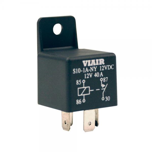
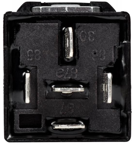
- Relay(s) – Automotive Four Pin Relay, rated for the current in the circuit, and pins numbered 85, 86, 87, and 30. If you have a relay that has pin 87a, this will work but be aware that pin 87a will be live with Battery Power when the lights are off; this is good if you are getting creative but not so if a wire or a tool hits it and things start to short out. Also, there is a relay with two Pin #87, so there will be 2 pins live when switch; check out what works for you.
Four Pin Relay
Five Pin Relay
- Hook up to the relay can be accomplished by one of two ways.
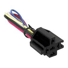
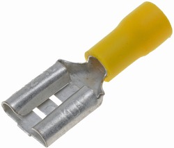
One - being a Relay Connector, 4 or 5 pin, easiest, designed to slip in place and comes with wire leads, but not as water tight as the other methods. The second way, my choice, is to use Female Spade Lugs.
Relay Connector
Spade Lug Connector, Female
- Power Wire - Automotive Wire – Do Not use Household Wire that is found at the local Hardware Store for automotive wiring.
Calculate the gauge needed for the total circuit draw. (Wattage / Volts = Amperage + 10%)
Buy enough Wire to run from the battery to where you want to mount the relays then on to the Lights; no real minimum or maximum on this wire length, all automotive runs are short runs. Get a couple feet more than you think you will need or a roll of 100 feet to cover future needs.
Note: Power Wire should be slightly oversized, (a larger gauge) for proper current flow, allowing the light to burn their brightest and last the longest. Smaller wire creates extra heat not only in the wire but in the component it is feeding, this will cause the lights to produce less light and burn out sooner because of the extra heat.
- Dash Switch Circuit Wire - Automotive Wire – buy enough to go from the inside Circuit panel to where you want to mount your switch, then to the relay under the hood, plus some for Indicator Light. The gauge of this wire should be 18 gauge but 16 gauge will work too. (Seems I always have 16 gauge wire around so use it if you have it) !
- Ground Wire - The size of the ground wire is dependent on the current in the circuit and should be sized the same as the power wires.
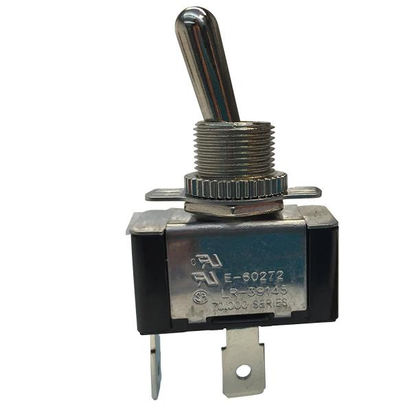
- Dash Switch – This is to control the Relay with a low amp circuit, the switch should be capable of handling 12 volts minimum; a 125 or 250-volt switch will work if it is the type you want. There are too many different types of switches to mention here but for the easiest type and related to the schematic buy a SPST (Single Pole Single Throw - On/Off) 12 volt switch. The two poles on the back side of the switch are for power (12 volts) and load (Relay).
SPST Switch
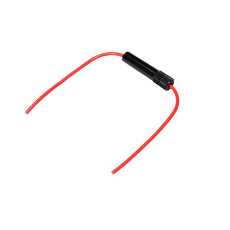
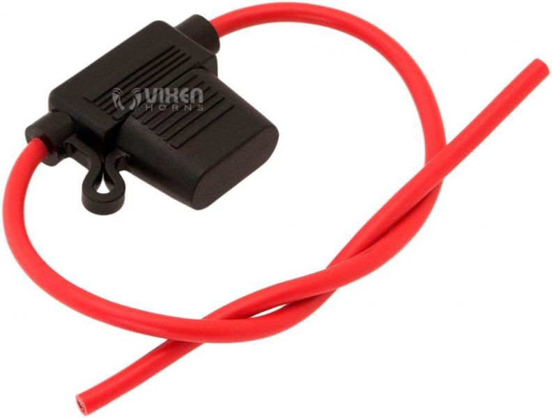
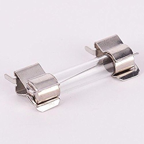
- Fuse Holders – Two in-line fuse holders, one for a low amperage fuse if you don't use the Fuse Tap, with wire sized for the gauge wire you are using for the Dash Switch and one for a higher amperage fuse, based on our total amperage draw for the main power from the battery to the really to the lights. Again, there are different Fuse Holders, Glass Tube Fuses are going away so Blade Type Fuses work, there maybe others.
Glass Fuse Holder, Inline
Blade Fuse Holder, Inline
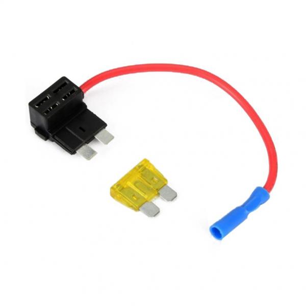
- Fuse Tap - A connector to tap a Circuit on the Circuit Panel inside of your vehicle. This can be used instead of one of the In-Line Fuse Holders but make sure there is a fuse built in.
Fuse Tap
- Fuses – Sized and rated for the smallest amperages rated component in the circuit. Two fuses are needed, a low amperage and a higher amperage but you need to calculate the rating for the loads.
Fuses Blade Fuse 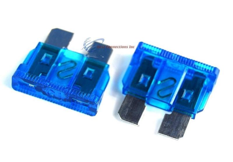
Glass Fuse
NOTES:
Activating Relay – Pin 85 on the Relay is used to activate it and 86 is used for the ground but both wires are required to make the Relay work. (Some Relays with only one of these pins will ground through the mounting hardware. It is a good idea to ground close to the battery or directly to the negative post on the battery via a terminal strip. (Pins 85 and 86, when there, are interchangeable)
The Install - Powering the Relay
– Everyone does things a little differently but this is how I do it and it has worked fine for many installs !
Step 1) Mount the Relay under the hood and the Dash Switch where you want them; it will simplify the wiring and guess work for the components.
Step 2) Using a DC Electrical Probe or Multimeter, find the power type you want to control the Relay via the Dash Switch.
1) Power On all of the time, so the Dash Switch will do the main power control
2) Power On with the key, so the power will be controlled by the ignition via the Dash Switch.
Hooking up the Switch with a low amperage circuit:
Most relays use very little amperage to activate, (approx. 250mA) or to turn on the circuit, so minimum gauge wire is required and a small amperage rated fuse is needed before the switch. I use 18 gauge wire and use 16 gauge when available to run the Power to the Dash Switch and to the Relay. I also use any fuse below 1 amp, sometime 2 amp but keep it small.
Step 3) Run a wire from the power point on the Circuit Panel (see Step 2) to one pin on the switch.
Note: It is suggested to use a SPST Switch with two poles for wires.
Step 4) From the second pin on the switch run two wires, one will go to the Relay and the second wire will go to the power side of the Indicator Light.
Note: Some Switches come with indicator Lights inside of them and all that is usually needed is a wire to ground, but every switch is a little different so double check what connection on the switch do what and hook up accordingly.
Step 5) Hook up the Ground of the Indicator Light – Most DC lights have two wires, one power coming from the switch and the second is the ground, the ground wire needs to be connected to a good metal grounded point on the body of the vehicle. Extend the wire as needed and this is the only ground that isn't going back to the battery directly.
Step 6) Connect the Wire from the Switch (Step 4) to pin 85 on the Relay.
Step 7) Run a 16/18-gauge wire from pin 86 to ground, use some external tooth star washers on the connection to ground, to make sure the connection makes contact with new metal.
Note: I like to use a Conductive Paste on the ground connection to keep things cleaner longer.
Test Point
Step 8) At this point you should be able to flip the Dash Switch and hear the Relay click, if you don't hear the clicking, re-check all of the connections or check to see if you hooked up power to the switch as a “Key–On Power†only, if so, turn on the key. Once you hear the Relay clicking then you are ready to hook up the power to the lights.
Hooking up Battery Power to run the lights:
Main Power from Battery - Calculate the amperage of the circuit - "Wattage / Voltage = Amperage"
Note:
[size="4" style="font-size: medium;"]The main fused power wire from the Battery to the Relay and on to the Lights should be sized based on the total amperage draw of the circuit. It is better to use a heavier gauge wire than a smaller gauge wire, i.e. 10-gauge instead of 12-gauge or 16-gauge instead of 18-gauge ! In my opinion there is no such thing as over kill when wiring higher current in a vehicle, bigger is better. (For safety reasons only) !
If using LED Bulbs or Lights, the amperage draw maybe less but the theory is the same. "Wattage / Voltage = Amperage"
Fuses – The fuse is there to protect the circuit and all of the components in the circuit and needs to be rated for the smallest component in the circuit plus a small margin for initial draw. MAKE SURE TO USE FUSES. i.e. a 30 amp rated Relay and 20 amp draw Lighting, with properly gauged wire, all add up to using a 20 amp fuse.
Step 9) Run a proper gauged wire from the battery positive post to Pin 30 on the Relay, make sure to have the properly sized fuse in-line with this wire.
Notes:
Mount the fuse close to the battery, this is a safety link and should blow out as first sign of a shorted circuit.
The proper gauged wire, this should be sized to the amperage draw of the highest current drawing component, in most cases the lights. Remember - “Wattage / Voltage = Amperage" i.e. 150 Watts light, divided by 12 volts, equals 12.5 amps.
LEDs do not use the high amperage that older Incandescent Bulbs do, so wire size can be reduced but the calculation is the same and the results should help in sizing the proper wire gauge so the LED run at their brightest without burning out !
Step 10) Run a proper gauge wire from the Relay, pin 87, to the first light and over to the second light, if there is one, allowing for routing the wire and connecting the wire to the second light. Easier to leave a little extra wire than to rerun the whole thing.
This wire should be the same size as the main power wire from the battery or larger.
]Step 11) Make the connection to the first light - To make a connection, strip some of the sheathing (outside covering) off of the power wire, making sure NOT to nick the strands of the wire. Strip the Power Wire at the light and wrap the Light Wire around the Power Wire where you stripped the sheathing. Start wrapping the wire to allow the heat shrink to slide over both wires, (make the connection as flat as possible – do not tin before wrapping) and solder this connection. Clean the connection and slip a piece of Heat Shrink, with adhesive inside, on to both wires but do not shrink it at this time just slide it over the joint.
Note: When soldering use a liquid flux if possible, there is no substitute. Paste Flux or Solder with Flux already in it will work, just watch the flow and make sure to get a hot solder joint and not burn it.
Step 12) Make the connection to the second light - Run the wire from the first light to the second, slide a piece of Heat Shrink on the wire before making the connection and soldering. (make sure to have a piece of Heat Shrink for both connections). Cut the wire to length, wrap the wires together lengthwise, solder the connection. Clean the connection, again do not shrink the Heat Shrink just slide it over the joint.
Note: See Flux, Note Step 11
Step 13) Grounding the Lights – You can ground the Lights or any component, to the closest metal that will allow you to secure a lug or you can do it the way I do. Run a ground wire, the same gauge as the power wire, from the Lights to the negative side of the battery or a grounding point/stud near the battery that will in turn be connected to the battery. Attach by preparing the wire and soldering the same as the Power Wire and don't forget the heat shrink before you solder.
Note: By running a separate Ground Wires back to the Battery you will reduce the main reason for Lighting Problems – POOR GROUNDING and in turn allow the lights to burn at their brightest and burn longer!
Test Point
Flip the switch and the lights should come on. If they don't you will need to re-check the Power Wire/Relay side of the circuit only, from the battery to the Relay and then from the Relay to the lights; that is if the Relay is still clicking from step 8. Don't forget the Fuse Holder needs a Fuse !
If the lights are working and everything looks good, clean the connections and shrink the Heat Shrink, I know you forgot about that ! Just get it done and your lights or other components will have a long life.
General Notes:
a) There are too many "if, an, nor, for's" to state every possible reason for the lights not working but usually if the wiring is OK then you need to check the Fuse or the Light Bulbs. If those are OK, re-check the wiring just to be sure, double-check all of the connections and the grounding point.
b) There are different type of heat shrink and most will work OK but the most important thing to remember is that you want to keep as much dirt and moisture out of the connections as possible. What is the best way; use heat shrink with adhesive inside of it and when you shrink it, the adhesive will melt and seal the joint. Just make sure the circuit works, clean the connections if you haven't done it yet and shrink the heat shrink !
c) The wire gauge that you use will depend on the total current (amperage) draw of the lights, usually based on the wattage of the lights, i.e highest current draw. Using a larger gauge wire is better than a smaller gauge wire because of safety factors and the larger gauge wire will allow the light to run at their brightest and last the longest.
IF all you have smaller gauge wire than what should be used, i.e. 16-gauge instead of 12-gauge, consider wiring the lights with two pieces of 16-gauge wire, each light would have its own power wire from the relay, both wires would go back to pin 87 on the Relay; just make sure the wire you use is up to the task of the amperage needed.
d) Always fuse the power wire from the battery, this is a safety measure and will save most of the components if there is a short circuit.
e) Always use a Relay to control the battery power. With the lower amperage draw with LEDs, you may think you do not need a relay but use one anyway it will separate the main power under the hood from the switching circuit inside of the vehicle and MAY stop a short circuit from causing a fire inside of the vehicle.
f) Here is a quick wire gauge reference based on amperage:
18-ga = 8 amps
16-ga = 10 amps
14-ga = 15 amps
12-ga = 20 amps
10-ga = 30 amps
Keep to these wire gauge sizes and you will not have a problem with under-rated wiring and the lights will burn their brightest and I think that is why we put lights on in the first place to be bright and to let people know we can do it, I did.
g) Just a point, the lengths of wire used in an Off-Road Light Circuit should have no effect on amperage draw in the circuit. There is loss in wire but not enough to affect the components.
h) When wiring to Battery Terminals, using too many wires on one bolt is both poor workmanship and can cause bad connection due to corrosion, There are a number of ways to fix this, one being a larger terminal that is setup with additional mounting points for the number and gauge wires you will be using (i.e. Buggman's Terminals) and two, my choice a Terminal Strip with a main fused wire for both the Power and Ground, going to the respective Battery Terminals. You can buy Terminal Strips with Fused Load side or you can add in-line fuses as required.
i) Remember the formula Wattage / Voltage = Amperage + 10% for safety factor. This results of this formula can be applied to all Components in the circuit, Lights, Wire, Relays, etc. !
I hope this isn't too confusing; I can get carried away very easily. I have tried to cover all aspects of the install and include different Components where I thought necessary.
All comments are welcome !
Any questions, e-mail me @ scrambler82@gmail.com
gsb/Scrambler82
Last edited on Mon Feb 12th, 2018 11:02 pm by Scrambler82
____________________
Ltr,
2003 EDGE, Std Cab, Steppie, E4 Red, 5sp, 4x
5" SuperLift, 33" x 12.50 x 15"
Hurst Shifter
Mod'd Backrack to fit Steppie
Front and Rear Bumpers by Custom 4x4 Fabrication, OK; now Mike's Welding and Fabrication.
Working on more Mods, just need more time, longer days would work !
|