410customs

Idahome

Joined: Wed May 2nd, 2018
Posts: 2165
Name: Jamie ... Occupation: Elevator Design Worlds Tallest Buildings ... Interests: Ranger Based Vehicles and OFFROAD ...
Reputation Points: 2165

|
This information was used to finish a 2002 Sport trac to 5.0 V8 AWD Conversion
This is how you fix the speedometer for 2002+ drivetrain conversions in our Ranger Based Vehicles
You will need a Dakota Digital Speedometer calibration unit, SGI 100BT (or similar)
Prepared by 410Customs
You are welcome!!
WIRING DAKOTA DIGITAL speedo calibrator into a 2002 Sport trac, Ranger, whatever you converted to a 5.0:
First up we need a VSS signal from the rear axle speed sensor.


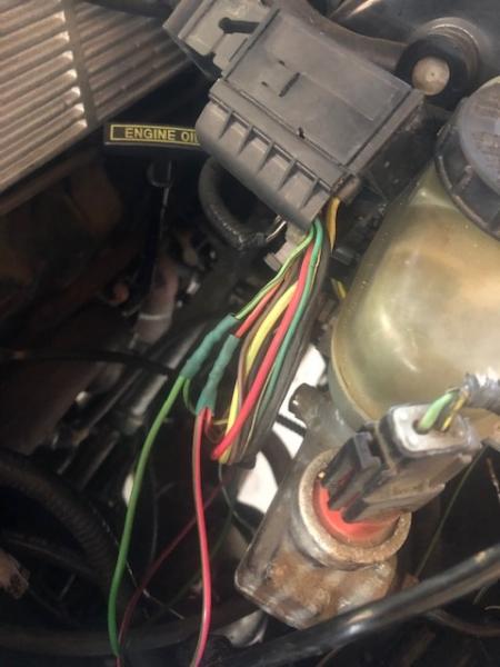
These wires can be found ONLY at the ABS pump on a 02 ST:
Pink/red is VSS +
Light green / black is VSS - (we do not even need this wire, but I did not know that yet)

So we TAP into these wires, LEAVE THEM CONNECTED TO THE ABS PUMP otherwise no more abs brakes for you
I only cut them so I could add heat shrink, all joints are soldered and the battery is disconnected!!!!
Run these wires into the cab through the firewall and up to behind the stereo where the GEM module resides.
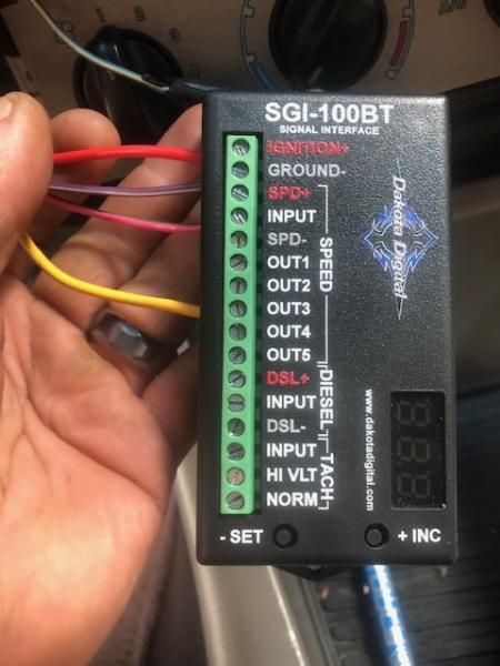
The PINK/RED VSS signal + feed goes to the speed input terminal on the dakota box
The light green with black wire turns out, is not needed.

Now that we have a speed sensor signal in we need a corrected speed sensor signal out, This is the grey/black wire circuit 679 found on connector c2001a at the GEM

Seen here:

We SPLICE into this wire, do not cut it, the GEM module, PCM, Speed control servo, 4x4cm, overhead console and instrument cluster will all need to see this signal
I ran a short yellow wire to the grey/black and hooked it to terminal OUTPUT3 on the Dakota box
Now the dakota box needs a power and a ground, we want hot in start or run:

Again we TAP into the RD/YE wire for power, run that wire to the Dakota IGNITION+ terminal
Tap into the BK/W wire for ground, run that wire to the Dakota GROUND - terminal

Red is 12V+, purple/w is my ground, Pink/red is the VSS + signal from the rear axle (abs pump), and the yellow wire is our output to grey/bk 679 at GEM
Red power wire gets TAPPED into here, to the Red/Y at the gem

and hard to see but our yellow wire is tapped into the grey/black feed at the Gem. Don't put your splice as close as I did

The wiring is DONE!!
Now you need to setup your Dakota box so it will work for us with application 3
referring to the instructions found here: https://www.dakotadigital.com/pdf/sgi-100BT.pdf
Set the Dakota box to convert a high signal to a low signal (H-L) or application 3
Any signal over 32000 ppm is considered a HIGH signal (for us its 77,760ppm)
Any signal under 32000 is considered a LOW signal (for us the target is 8000ppm)
Application 3 settings seen here:

Set the CAL value to 1.65
Using output 3 will send 1/16 of that value to the black/grey 679 vss+ signal to modules.
The math goes like this:
Figuring out the VSS PPM:
Tire revolutions per mile x ring gear teeth = VSS generated signal to ABS pump
29" tire revolves 720 times in a mile
Our 8.8 ring gear has 108 teeth, so
720 x 108 = 77,760 pulses per mile (ppm)
being sent to the ABS motor from the rear axle VSS
77,760 needs to be factored up so that 1/16 of it is close to the target 8000ppm.
(1/16 of something is the same as saying multiply by 0.0625)
So
(77,760 x __________ ) x 0.0625 = 8000
77760 x 1.65 = 128,304
128,304 x 0.0625 = 8019 pretty dang close
Can also say it like this:
1/16 of 128,304 = 8019 PPM
That is how we get our CAL value of 1.65 and know we need to use output3 which is 1/16 of that value
You can adjust for your tire size rolling diameter!! Drive around with a gps and check your speed. You can ADD or SUBTRACT from the CAL value while you drive to fine tune your speed signal!
The SGI-100bt is bluetooth and with the Dakota app on your phone you can change these settings via bluetooth or using the buttons on the Dakota box.....
VERY HAPPY!
Any questions? LMFAO
Some helpful info, this is for a 2002 sport trac, others will be similar:


You can wire this into ANY FORD and use ANY SPEED SENSOR for the signal, you can use a Talhousing mounted VSS, you can use a transmission mounted OSS, you can use a front wheel mounted speed sensor or like we did and use the VSS found in the 8.8 axle. You will have to figure out how many pulses per mile your speed sensor is sending out, then you can choose the correct input and outputs for the Dakota box.
____________________
I build custom RBV, specializing in drivetrain conversions, wiring, suspension and complete custom trucks
|


