| PM | Quote | Reply | Full Topic |
Gunslinger
Joined: Sat Nov 4th, 2017
Posts: 426
Status:
Offline
Reputation: 

Reputation Points: $user_rep
The circuit schematic I posted earlier only half works. It does work, but only when the brake pedal is pressed. If the brake isn't pressed, the lights on the output are dark. I tell ya, coming up with a circuit that truly converts 3 bulb to 2 bulb after the fact is surprisingly difficult.
At some point, I had the revelation to run the relay in reverse. When we use relays, we usually only consider using them to send power to one or two different places. For most of us, we probably only use half the relay the majority of the time. Horns, aux lights, the like.
However, we can also use them to power one thing from two different sources. Let me show you what I mean.
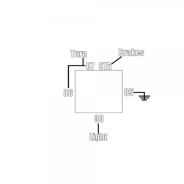
Usually we send power to 30, and send it through 87 or 87A, then to the device. Here, however, I'm connecting the lamp to pin 30, and I'm changing the source power via the actuation of the relay. This circuit right here does and doesn't work. It does succeed in changing which source is powering the lamp, but only for the duration of the signal. It doesn't allow for any 'dark' time when the turn signal is off while the brakes are still depressed.
That right there was the hardest part of designing this circuit, figuring out how to keep the relay energized long enough to keep power flowing from the turn signal circuit to the lamp without it switching back to the brake circuit before we want it to. I tried to do this without any exterior components, but ultimately failed to do so. See, it's easy for Ford to do it, as they can 'kill' the brake signal to the appropriate lamp with the same switch that activates the turn signals. They don't need complimentary components. Guys like me that do things after the fact, however, not so much. Not without rewiring the entire truck.
Now I may be crazy, but I'm not that crazy.
I dug around in my parts bin, did some more testing, and came up with this.

It's a bit more complex, but it does the job just fine. It's almost the same circuit as before, but the majority of the changes center around the relationship between pin 87 and 86, as well as between 86 and 85.
You'll notice that between 87 and 86, there's a diode. Between 85 and 86, a capacitor. The cap acts as an energy storage space and the diode prevents that energy from leaking out from where we want it to stay. The cap is charged by the turn signal's pulse, and has enough energy to keep the relay closed until the next pulse arrives.
These two components working together allows the combo light to flash while you're signaling, but return to being a brake light once you've finished you're turn.
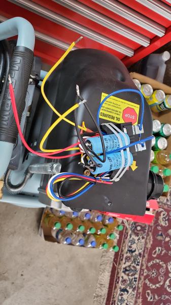
This is what all that looks like put together. The caps I used are rated for a max of 40v, and 2700uf. 2700uf is way more than what is needed, but that was the only size I had that worked. I had a 470uf that *almost* worked, but it didn't quite have enough to keep the relay closed. One around 800uf-1000uf would likely work just fine. The diode is just your standard silicon diode. They don't have to be anything special. Do pick a diode that is large in it's physical dimension. Makes it easier to work with and physically stronger. The actual specs don't matter too much. The relay doesn't draw much current (therefor the diode doesn't heat up much if at all), and the forward voltage drop is really inconsequential. You could probably use a schottky diode, too with equal results. Lucky for us, the voltage requirement on the relay's switching circuit is pretty forgiving.
Of course you can buy the components online if you so desire, or you can salvage them from old electronics. I hang onto old circuitboards just for this purpose. The diodes I got from an old PC power supply, and the capacitors I snagged from an old battery backup. That said, if you can't find one single cap big enough, you could wire up two or more in parallel if necessary. Or, you could be less stubborn than me and just buy a converter. You could probably also use a different type of cap all together.
Buy a good one though, as cheap china units suck out loud. My father can attest to that, as we tried to convert his combo signals to 3 way signals with one, and that didn't work out well for very long.
Anyway, enough of that.
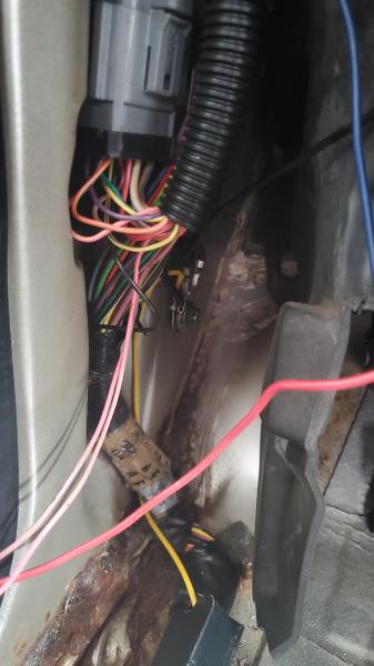
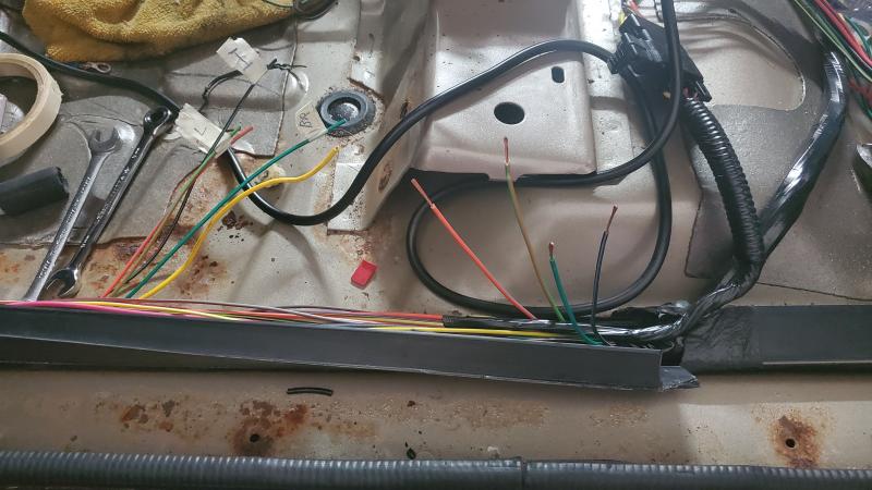
I tapped into the harness running along the driver's side, found all the wires that I need. Interior, park circuit, left and right signals, and brakes. Although it hurt to do, I chopped the wires in half so I could splice in a plug and use heatshrink to cover them up, rather than leaving them intact and only being able to wrap them up in tape. Worthy sacrifice for longevity, if you ask me. I did add one wire to that harness, a ground. The ground wire I ran over to the driver's side footwell and added onto a dedicated grounding point. The only reason I chose yellow, is I had a nice long piece of hookup wire lying around that happened to be the right size. I prefer black for ground, but at the end of the day I believe it's the quality of the connection that's more important than the color of the wire.
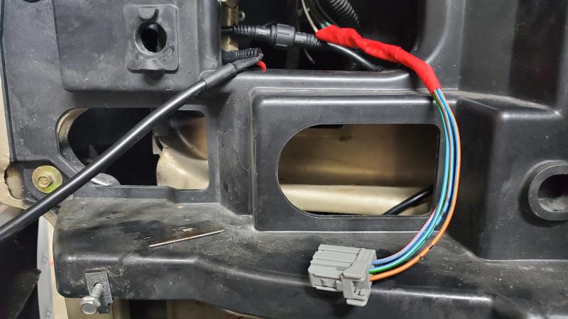
Also. I have the front reassembled. The truck's headerpanel did require some light modification. Some of you 98-00 owners may recall that each lamp's cables is run through it's own seperate hole in the panel. With the sequential modules, I wound up having to run them all through one. I probably could have done it the factory way, but I didn't see the gain for doing it that way over my way.
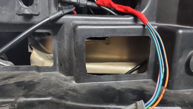
This is the modification. I had to take a razor blade (fresh new one) and carve out the rounded edge of the hole into a square one. This is done for clearance. Without it, the wires wound up almost getting crushed between the socket and the panel itself. After that, I tucked things away and called it a day.
Not quite sure how it wound up being vertical instead of horizontal. You get the idea, though. That said, I'm happy with the end result. You'll notice the brushguard is missing. It's reinstalled now, but I had to remove it in order to get the housings out. I love that guard and how it looks, but man does it make it a pain to get to anything. Good luck changing headlight bulbs, I guess?
I'm going to make more progress today.
Oh, some of you may notice the rust on the floorboard. That's getting addressed with some wire brush and paint. Maybe I'll get the floor in, today!
Next weekend, I'm getting a 4 day weekend, so expect to see even more progress in the coming days.
____________________
1999 Ford Ranger XLT - 3.0 V6 4x4 - Loaded (Totaled) 143k. Rest in Peace, Gold Dust.