| PM | Quote | Reply | Full Topic |
Gunslinger

Joined: Sat Nov 4th, 2017
Posts: 426
Status:
Offline
Reputation: 

Reputation Points: $user_rep
Thought about it, and decided to do it a little differently. Schem implies a standard 5 pin is used, but the mini relay would suffice if your output current is low.
Originally, I had the brake signal flow through the relay from 30 to 87A uninterrupted. The turn signal, signal, would then energize the relay and kick out the brake light. This did work, but resulted in the "converted" output being the opposite of the rest of the vehicle, which is unnacceptable. I mulled around a way or two and this is what I came up with.
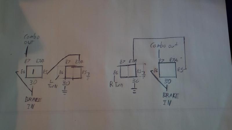
Here's what's going on. L/R are mirror images of one another, essentially.
Pin 30 on relay 1 connects to the brake signal. Pin 86 is tied to pin 30. Pin 87 goes to the bulb desired, the 'combo out' short for 'combination output'.
Pin 85, on the other hand, leads to relay 2, pin 87A. Pin 30 and 85 on relay 2 are tied to ground. Pin 86 @ relay 2 connects to either the left or right turn signal circuit, whichever is needed.
When the brakes are applied, relay 1 energizes, allowing the current to flow through 30 and out to 87, illuminating the lamp. The relay's ground flows through relay 2 uninterrupted, out to pin 30. When the turn signal begins, however, the turn signal current energizes relay 2, disconnecting Relay 1's ground, killing the light.
That's the theory. I haven't cracked out the jumper wires and tested it, yet.
____________________
1999 Ford Ranger XLT - 3.0 V6 4x4 - Loaded (Totaled) 143k. Rest in Peace, Gold Dust.