| PM | Quote | Reply | Full Topic |
Gunslinger
Joined: Sat Nov 4th, 2017
Posts: 426
Status:
Offline
Reputation: 

Reputation Points: $user_rep
PSA
 : There appears to be a bit of confusion whether or not this mod will work with LEDs. The short answer is: Yes, it will. I know this because my truck only has halogen fog lights and head lights, all the other bulbs being LEDs. The long answer, however, is: Maybe, it depends. The problem is that this mod depends on polarity. 194s have a peculiar habit that I can't quite describe or understand, but suffice it to say it's this behavior that makes the mod work. LEDs, or Light Emitting Diodes will only conduct and illuminate going one way. The LEDs you need to make this mod work will have extra circuitry inside them to circumvent this problem, allowing it to work no matter which way it's plugged in. Buy non-polarity sensitive LEDs and you will be in good shape.
This was one of the first mods to my '99 and it sure adds a bit of cool factor to every truck it's done to. This will work with any Ranger that has a 194/921 corner light and at least one forward turn signal.
Doing some research, it seems that there are several color combinations of wires, so I can't tell you exactly which color wire to cut or solder to, which complicates things just a little. However, I have devised a way to create a method that makes it easy to know which wires are the ones you want.
First, take your headlights and corner lights off. Each generation of Ranger is different, but how to remove these lenses can be found all over the web, so I won't bore you with that.
After these are apart, gather some tools.
-Wire Cutters
-Wire Strippers (auto or manual, I prefer auto)
-Soldering Iron w/ solder (TIP: if the solder isn't flowing easily, use flux to assist the process. Flux cleans corrosion and oxide layers off the copper and allows the solder to quickly flow on easily)
-Heat shrink & quality UL Listed electrical tape. The cheap stuff doesn't last.
-A lighter OR hairdryer/heat gun
-Multi-meter OR test light
Now, since each truck will be different for the most part, I unfortunately can't feasibly provide a look at the process on the vehicle. Thankfully, the actual mod itself is dirt simple to do and anyone with these tools and knows how to use them can easily accomplish this.
Before we begin, however, we need to understand the goal of this mod, beyond the added function. The ground wire of the 194/921 side marker needs to be cut. The wire on the socket then needs to be brought over to the turn signal wire on its respective side and bridged on. Simple, yes? If you have a wiring diagram for your year model ranger, you can skip the rest of this and do as I just described. For the rest of us, however, here's a way to see what you have.
Start by pulling out the bulb in the side marker's socket. You will see two sets of contacts. One side is positive, the other is negative. We need to figure out which is which. Generally speaking, black is ground, but I've seen on a couple occasions where this isn't true. If you have a multi-meter, set it to measure either ohms or continuity. Touch one probe to a grounding terminal (such as the negative battery terminal) or somewhere with bare metal. A wire brush may be useful here.
NOTE: Have all the light switches OFF during this test. Also, try not to short out both sets of contacts. Even though everything should be off, better safe than sorry.
You should find that one of the contacts reads very close to zero ohms resistance. This is the ground wire that needs to be cut.
Don't have a multi-meter? Grab a test light. Clip one end to the positive battery terminal, then probe both sides of the socket until it lights up. When it does, you've found its path to ground.
Cut the ground wire and tape up or preferably heat-shrink the end that goes to the truck. Next, strip the end of the wire on the socket and extend it to comfortably reach the turn signal's socket. If yours has multiple turn signals, pick either. It doesn't matter which one.
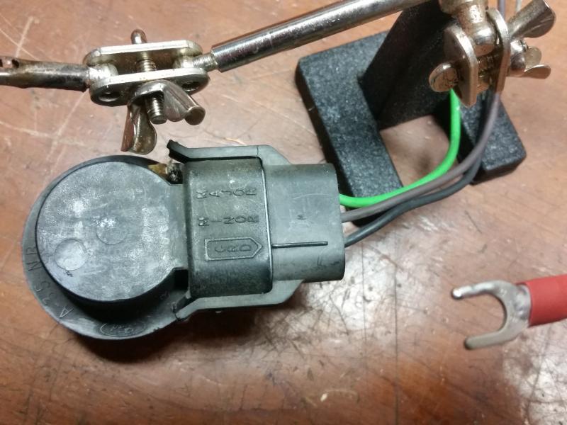
Now, here's where I can actually post a picture to illustrate a point. Turn the socket over and on its bottom you should see three markings. GND, Minor, and Major.
GND means ground, minor is the dim filament (used for running lights) and major is the bright filament, used for turn signals. We want the wire indicated as 'Major'.
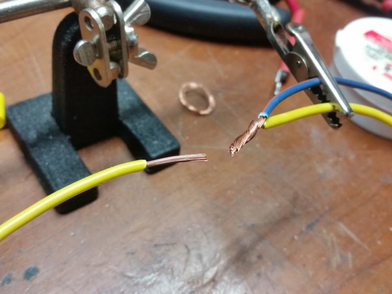
Now, there's two different ways to go about attaching the wire we extended to this turn signal wire. We can cut and strip both ends, twist and solder the two together as shown in the top photo, or alternatively, we can use a set of automatic wire strippers to make a gap in the wire, leaving it intact, and wrap the new wire around it, then solder. I have not soldered the wires in these photos so you can clearly see what's been done. The wires you see being used are scrap pieces being used for demonstration purposes.

There's a few pros and cons to each.
With the first solution, we can use heat shrink to secure the connections. Heat shrink lasts forever and a day, but we have cut the wire and reconnected it. This isn't necessarily a bad thing, but if the solder joint is bad, then it will break. Ensure the solder joint is nice and strong.
Tip: You know you have enough solder when it's tough to see the individual strands in the wires. If you can clearly make them out, you don't have enough.
With the second method, this leaves the wire intact, but we miss out on being able to utilize our heat shrink. In my experience, tape doesn't cope well with heat and water. I recommend the first method for longevity.
Whichever way you decide on, ensure the connection is secure and it will last.
Tip: It's a good idea to disconnect the negative battery terminal and tuck it away when cutting wires and putting them back together again. Doing this eliminates the possibility of shorting something out.
-A quick 'thank you' to user mhoward for catching my grammar mistakes. The difference between what you think you're typing and what you're really typing is amazing sometimes.
Last edited on Sun Nov 26th, 2017 08:10 pm by TheArcticWolf1911
____________________
1999 Ford Ranger XLT - 3.0 V6 4x4 - Loaded (Totaled) 143k. Rest in Peace, Gold Dust.