| PM | Quote | Reply | Full Topic |
Gunslinger

Joined: Sat Nov 4th, 2017
Posts: 426
Status:
Offline
Reputation: 

Reputation Points: $user_rep
Let's talk about the 'why' first. Why complicate things?
Well, to start with, crimp connectors are not the be-all-to-end-all, plain and simple. No matter how tight you crimp them, a wire can always be pulled loose, and they are always susceptible to corrosion, causing problems in your projects.
Several years ago, my father worked for a tow truck company. The cab lights were installed using crimp type connectors. Frequently, they'd find the lights stopped working and would need to be redone. These problems stopped after he ditched the crimp connectors in favor of a soldering iron. Anecdotal evidence? Yes, but my point remains. A job worth doing is one doing right.
When it gets down to it, a crimp connector is a piece of metal squashed onto another piece of metal. No more, no less. Unfortunately, we can't get around using them in some cases, so what's a guy to do?
Grab your soldering iron and follow me.
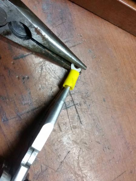
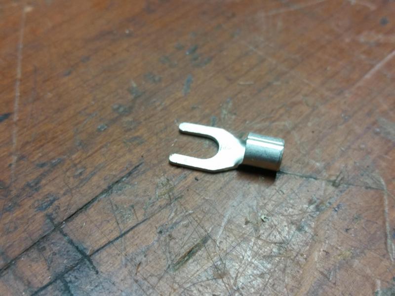
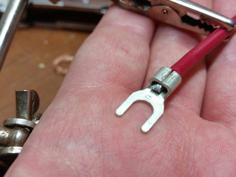
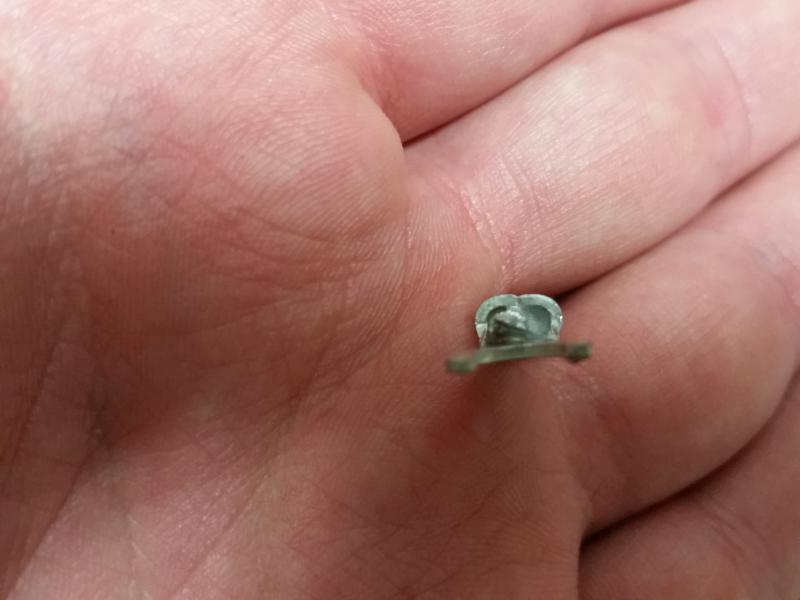
Good, you made it. Plug in your soldering iron and let it come up to temperature while we prep the connector and wire end to be soldered. First thing we need to deal with is this pesky plastic piece. A set of needle nose pliers can be used here. One pair gets put inside the plastic piece, gripping only the plastic, and the other on the connector itself. Simply pull and the plastic will come off. It can be cut off, but it is a chore and a half to do. This process will work for any connector similar in design to the one shown here, whether it be red, blue, or yellow, which indicates connector gauge size.
Note: This process does not work well with 'butt' connectors. Twist and solder your wires together using either the Western Union or NASA technique. Choice is yours.
PSA
 : I've seen a few videos, namely by Scotty Kilmer on youtube, where he has used wire nuts to join wires together. These types of "connectors" are not even close to suitable for automotive applications, even for a prototyping scenario. The connection is weaker than crimping and just as susceptible to corrosion. Wire nuts are not designed to be jostled around in a vehicle. They were meant for home applications, such as connecting fixtures.
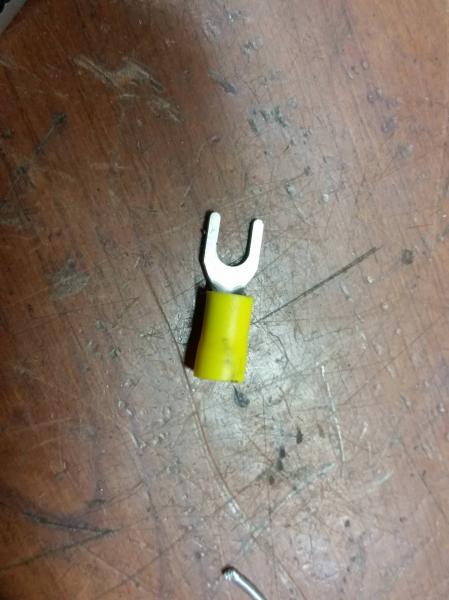
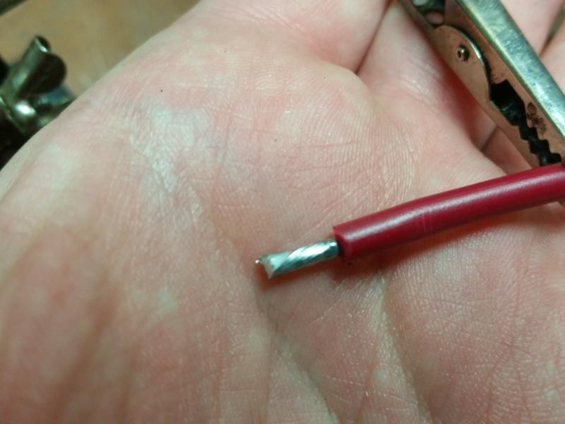
Next, strip the end of the wire. I prefer automatic wire strippers, but any kind will do. With the end of the wire stripped, I recommend tinning the wire first. This will make the process go quicker, but not strictly necessary.
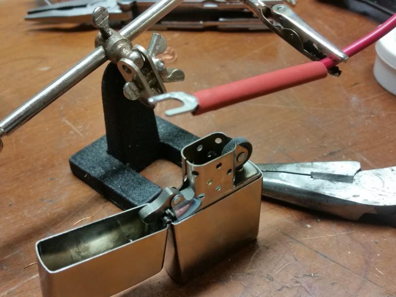
Remember: Slide your heat shrink over the wire BEFORE you solder on the connector, while keeping it far enough away that it does not shrink prematurely. This will protect against the elements and short circuits. In the case of spade connectors, ensure the heat shrink slides up over the entirety of the female connector. Slide the heat shrink only over the solder lug on the male side. An extra layer of heat shrink can be used on top if desired. This is a good idea to do when the connection will be exposed to the elements.
Slide the connector over and crimp it down over the wire. This will hold it steady while we solder. Use the tip of the iron to heat the connector, allowing the solder on the wire to melt. Add more solder if desired, the end goal being a nice fillet of solder inside the connector. Once the connector is cool enough to touch, slide the heat shrink over and shrink with either a lighter or hairdryer/heat gun.
The end result is a connector that is much stronger than crimping alone, and will also fair better in the elements.
Last edited on Sat Nov 25th, 2017 07:08 pm by TheArcticWolf1911
____________________
1999 Ford Ranger XLT - 3.0 V6 4x4 - Loaded (Totaled) 143k. Rest in Peace, Gold Dust.