| PM | Quote | Reply | Full Topic |
Old Bastard !

Joined: Fri Dec 22nd, 2017
Location: California USA
Posts: 2108
Status:
Offline
Reputation: 
Reputation Points: $user_rep
Scrambler82 wrote:
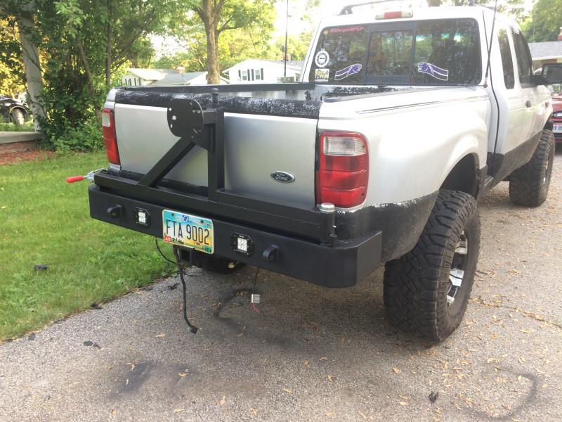
Looked at your Tire Carrier, how's that working out ?
Just asking, why didn't you put the passenger side brace up at an angle ?
Also , after reading the thread again, not all of it, I noticed you had a feedback problem in your CB, did you get the straightened out ?
Great job, a lot of work, and this truck will be brand new.
Ltr
Tire carrier is working great! No sagging or rattles yet. Still haven't wired the LED pods though :O. As far as the bracing goes, I kinda just didn't think the upright needed any more support. The passenger side "brace" was added so that I would have more surface to weld between the spindle tube and the tire carrier, but I thought it looked better if it ran all the way to the upright.
The CB issue was frustrating! It ended up being a bad ground at the antenna (base was all corroded inside). I found that out after rewiring everything, running new COAX, and having the transmitter serviced. But, it works well now haha
Thanks!
The Tirecarrier looks good and as I said before your welding looks good, I just was wondered.
The one on my Jeep, has both supports at an angle, the passenger side brace is welded similar to yours, it is connected to the Pivot Point, so the idea is the same.
Uses Wheel Bearing for the Pivot, works great just need to remember to grease it once in a while.
CBs, used to be a big thing, everyone had Handles, funny how things go ! Cell Phones put a major kink in the CB Industry !
Anyway, Grounding is very important for the complete system, the Radio should have power and grounds straight to the battery, we used to use a piece of RG-8 Coax, positive in the middle and negative in the shield and the Antenna Mount should be ground to the frame, not the bumper, not the body, but a 5/8" or larger braided ground strap back tot eh frame, where the connections should be to are metal and anti corrosion paste added.
The ground to the frame helps setup the ground plane that the antenna works off of, a good ground plane and a good reflecting signal means a good SWR and a strong signal out.
have you ever checked the Standing Wave Ratio (SWR) of the system ? It should be checked at multiple point in the transmission line, i.e. coax. Start at the back of the radio, no further away than 12 to 18 inches, then again at the antenna.
Ok got carried away... kind of like Radio Stuff !
Last thing, the Side Steps/Rock Sliders... I always wanted something like you built, tire to tire type of thing, protecting the Steppie Bed, with heavy Rectangular tube slider section and that added riser to protect the body, sweet stuff !
Keep up the good work, looking great, pictures, pictures, pictures !
Ltr
____________________
Ltr,
2003 EDGE, Std Cab, Steppie, E4 Red, 5sp, 4x
5" SuperLift, 33" x 12.50 x 15"
Hurst Shifter
Mod'd Backrack to fit Steppie
Front and Rear Bumpers by Custom 4x4 Fabrication, OK; now Mike's Welding and Fabrication.
Working on more Mods, just need more time, longer days would work !